Mechanical Splicing
Bureau Built constructions
More and more engineers are specifying mechanical rebar connections over lap splices. They've found that mechanical connections afford a reliability and consistency that can't be found with lap splicing.
 |
The use of reinforcing bar couplers or mechanical splices in reinforced concrete construction is on the increase. Mechanical splices are selected for various reasons: where lapped splices are impractical due to congestion of reinforcement at construction joints and increasingly for practical considerations to enable build-ability, thereby simplifying construction.
The Indian construction industry has felt the immediate need, and is encouraging
|
the builders to use mechanical splices for use in many major infrastructure and multi-storied construction projects. At present, the splices for reinforcing bars are by imported know-how, and the American code of practice is taken as reference for acceptance criteria for certification on the performance of couplers.
Large diameter steel reinforcing bars used in concrete members, when normally lapped as done for small diameter bars require about 15% more than that when used as a single bar. The lapping cannot be avoided as the bars come in standard lengths of 18-12 m. The practice of lapping large diameter bars has been discontinued, considering the congestion of reinforcing bars and economy, by providing ‘Mechanical Splices/Couplers’. Lapping of reinforcing bars has long been considered an effective, economical splicing method, but today’s more demanding concrete designs are forcing builders to consider alternatives.
Mechanical splices are mechanical connections between two pieces of reinforcing steel that enable the bars to behave in a manner similar to continuous lengths of reinforcing steel bars. Mechanical splices join rebar end-to-end, providing many of the advantages of a continuous piece of rebar. Years ago, arc welding was the only method of achieving continuity. Today, a myriad of mechanical splices are available to ensure that a precise, reliable connection can be quickly and easily made.
Mechanical splices are more reliable than lap splices because they do not depend on concrete for load transfer. Further, mechanical splices are stronger than lap splices: ACI requirements for mechanical splices are at least 25% higher than typical design strengths for lap splices.
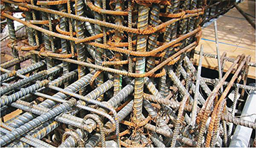 |
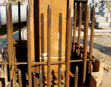
| Congestion due to lap splicing |
Mechanical splices provide superior strength during load transfer. Superior cyclic performance and greater structural integrity during manmade, seismic or other natural events are other advantages of mechanical splices.
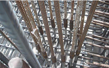 |
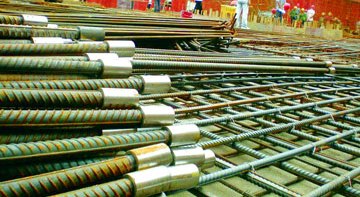
| Reinforcement with Mechanical Splicing |
From the structural perspective, the most important benefit of using mechanical splices is to ensure load path continuity of the structural reinforcement independent of the condition or existence of the concrete. Additionally, mechanical splices reduce congestion of the reinforcing concrete by eliminating laps.
Laps increase the steel/concrete ratio and create problems while placing the bar and during concrete consolidation. Elimination of laps also frees space for post tensioning operations. From the design perspective, mechanical splices can be relied upon to improve steel-to-concrete ratios, which assist in delivering a consistent ratio under 8%. When using laps, working with small diameter reinforcing bars may require the use of larger column dimensions to accommodate a greater quantity of bars. Using mechanical splices allows the option of using larger diameter rebar in a smaller column, while minimizing congestion.
Reduced column size results in a more efficient optimum use of floor space – an extremely beneficial economic and design consideration. Efforts to evaluate the comparative costs of using lap splicing and mechanical splicing in concrete construction show that the reputation of splices for adding substantial cost to a construction budget is unfounded. A recent study conducted by Cagley & Associates of two structures showed that the additional cost of mechanical splicing, when integrated as part of the original design, is less than 0.2%. Further, only column steel was considered. According to the authors, had beam steel been mechanically spliced and included in the comparison, the comparative costs would have been equal.
Mechanical splicing does away with the tedious calculations needed to determine proper lap lengths, and their potential errors. Because mechanical splices do not overlap, less rebar is used, reducing materials costs. Mechanical splices also are fast to install with no specialized labour. Easier placement of the bars saves valuable crane time, and helps to keep labour costs to a minimum while maintaining or accelerating project schedules.
Benefits of Mechanical Splicing
Mechanical systems are more reliable than lap systems because they don’t depend on the concrete for load transfer. They offer greater structural integrity, strength and toughness during man-made, seismic or other natural events. Codes require that mechanical splices deliver higher performance than typical design lengths for lap splices. This is typically 125% to 150% greater capacity provided by the mechanical splice versus the lap splice.
 |
- Mechanical systems are more reliable than lap systems because they don't depend on the concrete for load transfer.
- Mechanical connections offer greater structural integrity. Mechanical splices offer strength and toughness during man-made, seismic or other natural events.
- Codes require that mechanical splices deliver higher performance than typical design lengths for lap splices. This is typically 125% to 150% greater capacity* provided by the mechanical splice versus the lap splice.
- Lap splicing increases rebar congestion at the lap zone and one of the major causes for forming rock pockets and voids in the concrete. Mechanical splices eliminate these congestion problems and will make the overall job more cost effective through minimized job site problems.
- Building codes stipulate a steel ratio and this makes it nearly impossible to achieve a balanced design with lap splicing. Mechanical splices allow the designer to achieve an ideal balance of steel and concrete by eliminating the additional rebar in the lap zone.
- Working with “small” diameter reinforcing bars may require the use of larger column dimensions to accommodate a greater quantity of bars. Using mechanical splices allows the option of larger diameter rebar in a smaller column while minimizing congestion. This reduced column size results in a more efficient design and an optimum use of floor space.
- Mechanical splices eliminate tedious lap calculations.
- Mechanical splices are fast and easy to install and require no specialized skilled labour.
- Mechanical splices are cost effective by reducing labour costs and accelerating job schedules.
- Dowel bar substitutes reduce labour on site, formwork costs and increase job site safety.
- Bar terminators eliminate congestion and simplify bar placing.
- Repair splices eliminate the cost of breaking away massive amounts of concrete.
Lap Splicing Vs Mechanical Splicing
For almost 100 years, construction practices in the building of concrete structures have focused on the use of steel reinforcement to transfer tension and shear forces. Lap splicing has become the traditional method of connecting the steel reinforcing bars, largely due to a misconception that lap splicing is “no-cost” splicing. Lap splicing requires the overlapping of two parallel bars. The overlap load transfer mechanism takes advantage of the bond between the steel and the concrete to transfer the load. The load in one bar is transferred to the concrete, and then from the concrete to the ongoing bar. The bond is largely influenced by deformations (ribs) on the surface of the reinforcing bar.
Continuing research, more demanding designs in concrete construction, new materials, hybrid concrete/structural steel designs and other changes in the construction industry are calling for the use of alternatives to lap splicing. Concerns about lap splicing go to the very principles that are the basis for lap splicing. Lap splicing requires concrete to take tension and shear loads, though concrete is notoriously poor in handling tension and shear.
Because lap splices develop their strength from concrete cover, deterioration of concrete will inevitably lead to splice failure. One disadvantage of lap splices is that they offer poor cyclic performance in the inelastic range. In Snow Belt and coastal regions, corrosion of rebar can lead to delamination and spalling of the concrete cover. Without proper cover the lap splice becomes ineffective and the load path will be broken. Loss of load path continuity can be tragic.
A classic example is the Alfred P. Murrah Federal Building in Oklahoma City, which was destroyed by bomb in 1995. This building was well designed and built to standard requirements. Rebar were properly placed, concrete of correct strength, etc., but a catastrophic failure of the structure resulted from the removal of one column. In a reinforced concrete structure, there was no requirement for making bottom bars continuous from span to span. If support is removed, the girder fails. The progressive collapse occurred due to lack of continuity of reinforcing steel: the lapped splices failed. According to FEMA investigators, “65% to 85% of the collapse might have been avoided if continuity of reinforcement had been maintained.”1 Continuous reinforcement can be achieved either through the use of one continuous length of rebar or through mechanical splicing. Lap splices, then, can be considered structurally less reliable and design-constrictive, with many “hidden” costs. As a result, usage of mechanical splices – previously considered cost-prohibitive – is on the rise.
Trends toward tougher buildings, increased geography impacted by seismic zone mapping, and tenant desires for safer structures may also impact the potential value of a building. Inclusion of mechanical splices today may predate future load path continuity requirements.
Clearly, mechanical splices offer numerous advantages. The negligible short-term perceived economics of lap splicing are far outweighed by the many structural and economic benefits of mechanical splicing, including continuity of reinforcing steel and structural integrity. With many different types of mechanical splices on the market, designers can easily incorporate them into future plans.
Load Transfer
Generally, the transfer of load between reinforcing bars is achieved by lap splicing the bars. The load transfer mechanism for lap splicing is by cementitious bond and the effectiveness of lap connections is dependent upon the type of bar and the strength and quality of the concrete. Additionally, as the bars are laid side by side, the load transfer is indirect, whereas mechanical splices provide a direct in-line load transfer. Load testing the performance of lap splices is expensive and time dependent, as the reinforcement has to be cast in concrete. It is therefore seldom undertaken in practice.
In contrast, mechanical couplers are generally subject to extensive testing to meet the requirements of specific national standards, technical approvals or those of a state or national infrastructure owner.
The main technical requirements for mechanical splices are:
- Tensile strength and ductility under static loads; this is necessary to provide a factor of safety.
- Limitation of permanent set slip under static loads often referred to as slip; this is necessary to limit cracking of concrete.
- Cyclic loading performance; necessary for structures in seismic (earthquake) regions.
- Fatigue performance; necessary for structures subjected to repeated loading, such as bridge decks.
- Tensile Strength and Ductility
A margin of safety against failure of a splice is required and it is also desirable that a degree of ductility is available at the splice location in a structure. Lack of ductility could result in little warning of possible sudden failure of the connection. Ductility is particularly important when designing couplers for use in structures subject to seismic loading, especially if their intended use is within the plastic hinge zones.
The properties of the reinforcing bar used in conjunction with a coupler have a direct effect on the overall performance of the splice.
Permanent Set Slip
As concrete structures crack, the degree of the cracking under load is controlled by reinforcement provided by the designer. Design procedures for this are well-established in codes and regulations. For mechanical splices the most commonly agreed permanent set slip limit is 0.1mm. This is the limit in ISO 15835:2009 and is the accepted limit amongst many major infrastructure owners internationally.
The test specifications for mechanical splices vary, dependent upon the specifying authority and country and application. Where mechanical splices are considered for use, the designer should ascertain the required coupler performance criteria and consult with manufacturers who can provide expertise in the selection of an appropriate and economical system.
Types of Mechanical Splices
The three basic categories of mechanical splices comprise ‘tension-compression,’ which can resist both tensile and compressive forces, ‘compression only,’ also known as the ‘end-bearing’ mechanical splice, and ‘tension only’.
The various types of mechanical splices available include:
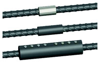
Coupler for Thread-Deformed Bar: This is a mechanical splice that requires special bars with threadlike rolled deformations over their entire length which meets ASTM A615. Splices are assembled with lock nuts and threaded couplers, then the nuts are tightened to a specified torque. Alternatively, the lock nuts can be omitted when the bars can be torqued together. Special hardware permits use for end anchorages in concrete or connection to structural steel members. Bars may be flame or saw-cut.
 |
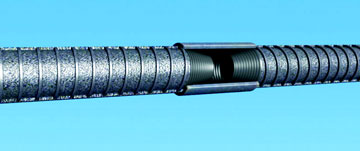
Taper-Threaded Coupler: This is a mechanical splice consisting of a taper-threaded coupler that joins reinforcing bars with matching taper threads. The coupler is installed by turning the bar or sleeve with wrenches to the manufacturer's specified torque. For splicing bent or curved bars, special three-piece position couplers are used. Adaptions permits use for end anchorages in concrete or connections to structural steel members. Bar ends may be shear-cut or saw-cut. Bar ends require taper threading over a specified length.
|
|
 |
Grout-Filled Coupling Sleeve: The double-frustum-shaped coupling sleeve is filled with a cement-based, non-shrink, high-early strength grout. Reinforcing bars to be spliced are inserted into the sleeve and butt at the centre of the sleeve. The space between bar and sleeve is filled with non-shrink grout to transfer forces between the deformed surface of the bars and the deformed interior surface of the sleeve. No special end preparation of the bars is required except for normal cleaning. The relatively wide sleeves also can accommodate minor bar misalignments, and combinations of different size bars.
Combo Grout-Filled/Threaded Sleeve: Primarily used for precast construction, this type of mechanical splice combines two common mechanical splicing techniques. One end of the sleeve is attached and secured to a reinforcing bar by means of threading. The splice is then completed when the other bar end is inserted into the sleeve and the space between the bar and the sleeve is filled with high-strength grout. The wide mouth opening of the sleeve allows for minor bar misalignment during erection. The wide mouth also allows for transitioning between different bar sizes.
 |
| Combo Grout-Filled/Threaded Sleeve |
Steel-Filled Coupling Sleeve: The steel-filled coupling sleeve is a mechanical splice in which molten metal or “steel filler” interlocks the grooves inside the sleeve with the deformations on the reinforcing bar. Special details permit use as end anchorages or connections to structural steel members. Shear-cut, flame-cut, or saw-cut ends of the bar can be used as the “steel filler” fills the space between the ends of the bar. However, a bar-end check is recommended.
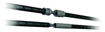
Non-Upset Straight Thread Coupler: This is a mechanical splice consisting of a coupler with internal straight threads at each end that joins two reinforcing bars with matching external threads. Because the cutting of threads reduces the net cross-sectional area of the reinforcing bar, some manufacturers use bars one size larger while other manufacturers use bars with tensile and yield strengths sufficient to overcome the loss of net area by thread cutting.
This type of splice is in three pieces (the two bar ends and the internally threaded coupler). These systems are also available as weld-on couplers, transitional couplers, and positional couplers.
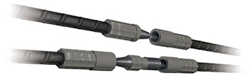
Upset Straight Thread Coupler: The cold-swaged threaded coupler consists of pre-threaded male and female components, which are swaged onto the reinforcing bars using a swaging press with special dies. No threads are required on the bar ends. Splicing of the bars is completed by installing one pre-threaded component into the other. A three-piece position coupler is available for splicing bent bars that cannot be rotated. Optional details include transition couplers for splicing different bar sizes, couplers used to connect bars to structural steel members, and couplers with flanges having nail holes. Threads are sealed and protected for future extension applications.
Cold-Swaged Coupling Sleeve: The cold-swaged coupling sleeve uses a hydraulic swaging press with special dies to deform the sleeve around the ends of the spliced reinforcing bars. This produces a positive mechanical interlock with the reinforcing bars. Bars to be spliced are inserted equal distances into the sleeve. Bars may be shear-cut, flame-cut, or saw-cut, however, a bar-end check is recommended. Bars of different sizes can be spliced with this system. This mechanical splice can also be used for joining reinforcing bars to structural steel members. Longer sleeves are required for splicing epoxy-coated reinforcing bars.
 |
| Cold-Swaged Coupling Sleeve |
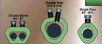
Coupling Sleeve with Shear Screw or Wedge: Designed primarily for splicing smaller bars, sizes #3 through #6, the coupling sleeve is oval in cross-section permitting the overlapping of two reinforcing bars of the same diameter in the sleeve. Each bar extends out of the sleeve about one bar diameter. After the sleeve is correctly positioned, a wedge-shaped round pin is driven through a hole in the flat face of the sleeve. The wedge passes between the bars and extends through a hole opposite the hole of insertion. The wedge pin is driven with a hand held hydraulic ram.
 |
 |
| Coupling Sleeve with Double Wedge |
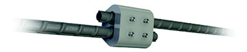
Coupling Sleeve with Double Wedge: This coupling sleeve consists of a ductile iron sleeve with two internal wedges. Two series of cone-pointed screws are arranged along the sleeve length, opposite a wedge-shaped profile in the sleeve. Each reinforcing bar extends out of the sleeve by approximately one bar diameter. No special bar end preparation is required. As the screws are tightened, they indent into the surface of the bars and wedge the barsinto the converging sides of the sleeve profile. Screws can be tightened suing suitable impact wrenches or hand-held ratchet wrenches. The heads of screw shear off at a prescribed tightening torque. Bar sizes #3 through #6 plus bars of different sizes or either uncoated or epoxy-coated can be spliced using this coupling sleeve.
Shear Screw Coupling Sleeve: This type of mechanical splice consists of a coupling sleeve with shear head screws which are designed to shear off at a specified torque. The reinforcing bars are inserted to meet at a stop in the centre of the coupling sleeve and the screws are tightened. The tightening process embeds the pointed screws into the bars. For one type splice, the screws force the bars into contact with internal gripping rails. For the other type of splice, the screws force the bars to wedge into the coupling sleeve's converging interior wall. The heads of the screws shear off at a prescribed tightening torque. The screws can be tightened using a standard socket wrench or pneumatic impact wrench. For making a splice between two fixed bars, coupling sleeves without a centre stop are available. This sleeve can be slipped completely onto one bar and subsequently repositioned over the two bar ends.
Straight Thread Coupler with Upset Bar Ends: This mechanical splice consists of forming heads on the ends of the reinforcing bars to be connected using a hydraulic machine from the splice manufacturer. This splice is designed to fit between closely-spaced bars. The upset bar ends are butted up to each other and are held in place using a male and female straight threaded coupler that is positioned onto the bars prior to forming the heads. The coupler is installed by turning either the male or female component and tightening to the manufacturer's recommended torque; no rotation of the bar is required. Bent or curved bars can be spliced with the same mechanical splice. Adaptations permit use for end anchorages in concrete or connections to threaded rods. Bar ends may be sheared, flame-cut or saw-cut.
Reasons for Using Mechanical Connections
Although lap splicing is certainly the most common way to splice rebar, using mechanical connections can increase productivity, safety, and structural integrity. Engineers and contractors should consider using mechanical connections if they want to:
- Increase structural integrity in seismic zones
- Increase structural integrity in load reversals
- Maintain a consistent steel-to concrete ratio
- Transfer loads independent of the concrete, allowing the rebar to react essentially as a continuous piece of unspliced rebar
- Reduce congestion
- Reduce crane time
- Eliminate the drilling of formwork
- Eliminate protruding rebar
References: