Basic PEMB Parameters and Specification Guidelines
BE Bureau
Pre Engineered Metal Buildings are generally versatile. With different available and possible framing systems, namely, clear span or modular, the building can be custom designed to suit the requirement. From manufacturing plants and warehouses, to offices and retail, steel buildings are applicable in almost every design. PEBs can virtually be designed compatible with any other construction material. Most metal buildings are purchased by the private sector, which seems to appreciate the advantages of proprietary pre-engineered buildings more readily than the public entities.

Advantages
There are many advantages of Pre Engineered Metal Buildings compared to conventional RCC buildings especially when it comes to low rise, large span and single floor structures. A few important are mentioned below:
Larger Spans- Their ability to span across larger distances makes them very appropriate and there are not many other types of gabled structures that can span 100 ft or more in a cost-effective manner. Use of built up sections make the structure weigh less and thus resulting in reduced cost.
Reduced Construction Time-Buildings are typically delivered in just a few weeks after approval of drawings. Foundation and anchor bolts are cast parallel with finished, ready for the site bolting. Studies have shown that in India the use of PEB will reduce the total construction time by at least 50%. This also allows faster occupancy and earlier realization of revenue.
Cost efficiency- As a system developed; fabricated to stringent quality specification in a factory, the pre engineered components will have better fit abilities and accuracy. These pre-engineered components are then transported and erected at site resulting in faster erection time and reduced labor cost. In addition, each structural member is designed for near-total efficiency, minimizing waste of material. Less labour and less material translate into lower cost. The estimates of this cost efficiency vary, but it is commonly assumed that pre-engineered buildings are 10 to 20 percent less expensive than conventional ones.
Easy to Expand- Buildings can be easily expanded in length by adding additional bays. Also expansion in width and height is possible by pre designing for future expansion. At the time of designing, it is recommended to keep the possible extension in both directions in mind. Assembly of different components of PEBs to be preferably bolted connections.
Low maintenance- A typical PEB building system, with prefinished structural members, metal panels and standing seam roof, is easy to maintain. Well covered and coated metal surfaces are easy to clean with excellent resistance against corrosion and discoloration resulting in better durability and low maintenance characteristics.
Quality Control- As buildings are manufactured completely in the factory under controlled conditions the quality is assured.
Single Source Responsibility-As the complete building package is supplied by a single vendor, compatibility of all the building components and accessories is assured. This is one of the major benefits of the pre engineered building systems.
Energy Efficient Roofing and Wall Systems- Buildings can be supplied with polyurethane insulated panels or fibre glass blankets insulation to achieve required "U" values. There are several different options for insulating a steel building, most of which are extremely efficient for heating and cooling. With proper insulation mechanism, overall energy consumption can also be considerably reduced along with noise level.
Architectural Versatility- Building can be supplied with various types of fascias, canopies, and curved eaves and are designed to receive pre cast concrete wall panels, curtain walls, block walls and other wall systems.
Durability and Longevity- Steel buildings are made to last. Unlike wood, steel has the ability to resist crack, twist, warp, rot, settle, or harbour insects. A metal building can stand up to Mother Nature, providing ultimate protection from the elements. Steel buildings are known for their protection against high winds, heavy snows, and other hazardous weather and last long.
Safety- With their enhanced resisting ability to adverse weather conditions, fire and heat, PEBs are comparatively safer than their other counterparts. In fact this fire safety often leads to insurance savings versus other construction materials.
Environment- PEBs are environment friendly and majority of the members used in constructions are made of recyclable products. The impact of steel on our environment is far less than using a non-renewable resource such as wood. Upon the completion of a project, the amount of unusable or non-recyclable material is very minimal, as opposed to other materials. Since steel buildings have such long life expectancies, they keep the impact to our environment minimal. Unlike other construction materials, a steel building can often been re-located and used for another application. Roofing of almost all PEBs can be designed as Cool Roofs and thus infusing green principles successfully.
Choice Influence
The Pre-engineered steel structures are resistant to moisture, adverse weather conditions, earthquakes, termites and fire that provide you with lifelong durability, safety and very low cost-maintenance. Pre-engineered steel building is very simple and economical with the necessary Architectural, Engineering and Construction with pre-engineered steel buildings.

Assuming that a metal building system is selected for the project at hand, the next milestone is choosing among the available types of pre-engineered primary framing. Proper selection of primary framing, the backbone of metal buildings, goes a long way toward a successful implementation of the design steps to follow. Some of the factors that influence the choice of main framing include-
|
Reduced construction time.
Flexibility of Expansion.
Large Clear Spans
Low maintenance
Energy Efficient Roofing and Wall systems
Architectural Versatility
Cost Affecting Factors
The idea of a pre-engineered building is to provide custom engineering to each situation, while having the basic and common components already
|
 |
- Dimensions of the building: width, length, and height
- Roof slope
- Required column-free clear spans
- Occupancy of the building and acceptability of exposed steel columns
- Proposed roof and wall materials
There are not many other types of gabled structures than can span 100 ft or more in a cost-effective manner. The inherent quality of the PEB themselves is a huge contributory factor for this favourable response.
designed and engineered. This provides a custom engineered project without completely "reinventing the wheel," and keeping costs to a minimal.
Planning and arranging different PEB building components are very important for the designer before proceeding with the design of each component. Building configurations significantly affect the building Stability and Cost;
- Main Frame configuration (orientation, type, roof slope, eave height)
- Roof purlins spacing
- Wall girts (connection & spacing)
- End wall system
- Expansion joints
- Bay spacing
- Bracing systems arrangement
- Mezzanine floor beams/columns (orientation & spacing)
- Crane systems
Basic Building Parameters
The basic parameters that define a pre-engineered building include Building Width, Building Length, Building Height, Roof Slope, End bay length, Interior bay length and Design Loads
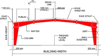
Building Width: Building width is defined as the distance from outside of eave strut of one sidewall to outside of eave strut of the opposite sidewall. Building width does not include the width of Lean-To buildings or roof extensions.
Building Length: The longitudinal length of the building measured from out to out of end wall steel lines.
Building Height: Building height is the eave height which usually is the distance from the bottom of the main frame column base plate to the top outer point of the eave strut. When columns are recessed or elevated from finished floor, eave height is the distance from finished floor level to top of eave strut.
Roof Slope: This is the angle of the roof with respect to the horizontal. The most common roof slopes are 0.5/10 and 1/10. Any practical roof slope is possible.
End bay length: The distance from outside of the outer flange of end wall columns to centre line of the first interior frame column.
Interior bay length: The distance between the centre lines of two adjacent interior main frame columns. The most common bay lengths are 6 m, 7.5 m and 9 m.
Design Loads
Design loads shall be as specified and set forth in the contract, and shall be in accordance relevant codes of practice and with the manufacturer's standard design practices. Design loads may include dead load, roof live loads, wind loads, seismic loads, collateral loads, auxiliary equipment loads, and/or other applied or specified loads.
- Dead Load - the actual weight of the building system supported by a given member.
- Roof Live Loads - loads produced by maintenance activities, rain, erection activities, and other movable or moving loads by not including wind, snow, seismic, crane, or dead loads.
- Roof Snow Loads - gravity load induced by the weight of snow or ice on the roof, assumed to act on the horizontal projection of the roof.
- Wind Loads - the loads on a structure induced by the forces of wind blowing from any horizontal direction.
- Collateral Loads - the weight of any non-moving equipment or material, such as ceilings, electrical or mechanical equipment, sprinkler systems, plumbing, or ceilings.
- Auxiliary Loads - dynamic loads induced by cranes, conveyors, or other material handling systems.
- Seismic Loads - horizontal loads acting in any direction on a structural system due to action of any earthquake.
- Floor Live Loads - loads induced on a floor system by occupants of a building and their furniture, equipment, etc.
Loads are applied in accordance with the latest American codes and standards applicable to pre-engineered buildings unless otherwise requested at the time of request for quotation.
Design Codes
American Design Codes AISC/MBMA
- Loads are applied in accordance with: The 2005 Edition of Low Building Systems Manual Metal Building Manufactures Association (MBMA)
- Hot rolled and Built up sections are designed in accordance with : Manual of Steel Construction, 9 Edition American Institute of Steel Construction (AISC)
- Cold-formed members are designed in accordance with : 1996 Edition of Cold Framed Steel Design Manual American Institute of Steel Construction (AISC)
- Welding is applied in accordance with : American welding Society (AWS D1.198) Structural welding Code-Steel
- AISI : American iron and steel institute specifications
- ANSI : American national standards institute specifications
- ASCE : American society of civil engineers
- UBC : Uniform building code
Indian Codes
- Loads are applied in accordance with:
IS-875 Part I: Code of practice for Design Dead Loads for Building and Structures IS-875
Part II: Code of practice for design Imposed Loads for Building and Structures IS-875
Part III: Code of practice for Design Wind Loads for Building and Structures IS-1893 (2002): Criteria for Earthquake Resistance Design of Structures.
- Hot rolled and built up sections are designed in accordance with :
ISO - 800(1984): Code of Practice for General Construction in Steel ISO - 800(2007): Code of Practice for General Construction in Steel Latest Revision
- Cold-formed members are designed in accordance with:
ISO - 801(1975): Code of Practice for use of Cold-Formed Light Gauge Steel Structure.
- Welding is applied in accordance with:
ISO - 816(1969): Code of Practice for use of Metal Arc Welding for General Construction.
Software
- Auto CAD
- STAAD Pro
- MBS
- Stru CAD
- 3D Max
- Tekla X-Steel
Specification Tips
General
- All framing members shall be shop fabricated for field bolted assembly. The surfaces of the bolted connections shall be smooth and free from burrs or distortions.
- All shop connections shall be in accordance with the manufacturer's standard design practices. Certification of welder qualifications will be furnished when required and specified in advance.
- All framing members, where necessary, shall carry an easily visible identifying mark.
Primary Framing
- Rigid Frame: All rigid frames shall be welded built-up "I" sections or hot-rolled sections. The columns and the rafters may be either uniform depth or tapered. Flanges shall be connected to webs by means of a continuous fillet weld on one side.
- End wall Frames: All end wall roof beams and end wall columns shall be cold-formed "C" sections, mill-rolled sections, or built-up "I" sections depending on design requirements.
- Plates, Stiffeners, etc.: All base plates splice plates, cap plates, and stiffeners shall be factory welded into place on the structural members.
- Bolt Holes, etc.: All base plates splice and flanges shall be shop fabricated to include bolt connection holes. Webs shall be shop fabricated to include bracing holes.
- Connections for secondary structural (purlins and girts) shall be by means of welded clips.
Secondary Framing
- Purlins and Girts: Purlins and girts shall be cold-formed "Z" sections with stiffened flanges. Flange stiffeners shall be sized to comply with the stipulated requirements. Purlin and girt flanges shall be unequal in width to allow for easier nesting during erection. They shall be pre-punched at the factory to provide for field bolting to the rigid frames. They shall be simple or continuous span as required by design. Connection bolts will install through the webs not flanges.
- Eave Struts: Eave Struts shall be unequal flange cold-formed "C" sections.
- Base Angle: A base member will be supplied by which the base of the wall covering may be attached to the perimeter of the slab. This member shall be secured to the concrete slab with ram-sets, expansion bolts, or equivalent anchors as shown on the drawings.
Bracing
- Diagonal Bracing: Diagonal bracing in the roof and sidewalls shall be used to remove longitudinal loads (wind, crane, etc.) from the structure. This bracing will be furnished to length and equipped with bevel washers and nuts at each end. It may consist of rods threaded each end or galvanized cable with suitable threaded end anchors. If load requirements so dictate, bracing may be of structural angle and/or pipe, bolted in place.
- Flange Braces: The compression flange of all primary framing shall be braced laterally with angles connecting to the webs of purlins or girts so that the flange compressive stress is within allowable limits for any combination of loading.
- Special Bracing: When diagonal bracing is not permitted in the sidewall, a rigid frame type portal or fixed base columns will be used. Wind bracing in the roof and/or walls need not be furnished where it can be shown that the diaphragm strength of the roof and/or wall covering is adequate to resist the applied wind forces.

Fasteners
- Structural Bolts: All bolts used in connections of secondary framing to primary framing shall be zinc plated ASTM A307 or ASTM A325 or equivalent as required by design.
- Fasteners for Roof Panels: All panels shall be attached to the secondary framing members by means of:
- Option #1: Self-drilling structural screws for roofs shall be carbon steel #12-14 x 1 1/4" Hex Washer Head, cadmium or zinc plated, with or without painted head, assembled with EPDM washer. These fasteners are applicable for use with fiberglass blanket insulation from 1" to 3" thick.
- Option #2: Self-drilling structural screws shall be carbon steel #12-14 x 1 1/2" Hex Washer Head, cadmium or zinc plated, with or without painted head, assembled with EPDM washer. These fasteners are applicable for use with fiberglass blanket insulation from 3 1/2" to 6" thick.
- Option #3: Self-tapping screws shall be #14 x 3/4" type "A" or "AB", zinc plated, painted or plain head assembled with a bonded or separate EPDM washer. These fasteners are applicable for use with fiberglass blanket insulation from 1" to 3" thick. Longer lengths are available. Pre-drilling is required.
Sealants and Closures
- Closure Strips: the corrugations of the roof and wall panels shall be filled with solid or closed cell, pre-formed rubber, and neoprene or polyethylene closures along the eave, ridge rake or base when required for weather tightness. Closures must be ordered separately.
- Sealants: Roof panels shall be sealed with 3/32" x 3/8" wide tape sealant. The material shall be a Butyl base elastic compound. The sealant shall have good adhesion to metal and be non-staining, noncorrosive, non-shrinking, non-oxidizing, non-toxic and non-volatile. The service temperature shall be from -60oF to +300oF. Optional 3/32" x 1" tape is available.
- Caulk: All gutter and downspout joints, rake flashing laps, ridge flashing laps, doors, windows, and louvers shall be sealed with white, burnished slate, or gray pigmented caulk of Butyl rubber base, or clear silicone.
Gutter, Flashing and Downspouts
- Gutters and Flashing: All standard exterior gutters are 26 gauge Galvalume steel or with painted finish in standard colors. Standard rake flashing is 26 gauge Galvalume steel or with painted finish in standard colors.
- Downspouts: All downspouts shall be 26 gauge Galvalume steel, rectangular in shape.
Flashing and Trim
- Flashing at the rake (parallel to roof panels) and high eave shall not compromise the integrity of the roof system by constricting movement due to thermal expansion and contraction.
- All flashing shall be manufactured from Galvalume steel, whether pre-painted or Galvalume.
Structural Painting
- All uncoated structural steel shall be cleaned of all foreign matter and loose scale and given a one mil coat of red oxide primer. Primer shall be applied by the use of airless handguns. Primer generally meets or exceeds the performance requirements of standard applicable codes.
- Light gauge steel members shall be shot blasted and pre-coated with one coat of red oxide primer. Some hand sprayed shop touch-up may be employed.
- Abrasions caused by handling after painting is to be expected. Primer shall be furnished to touch-up or field painting as specified in the contract documents.
Painted Steel Panels
- Base metal shall be 26 or 24 gauge Galvalume steel.
- Prime Coat: The base metal shall be pre-treated and then primed with an epoxy type primer for superior adhesion and superior resistance to corrosion.
|
 |
Erection and Installation
- The erection of the metal building components shall be performed by a qualified erector, using proper tools and equipment. Erector shall follow good, sound, safe procedures and guidelines and in accordance with any applicable federal, state or local laws.
- Erection of the roof system shall be in complete accordance with the Manufacturer's Safety and Erection Manual. Any deviation from this manual could result in damage to the roof system, for which Manufacturer will not be liable for repair or replacement.
- The erection manual shall include procedures and trim design variations to accommodate the out-of square and out-of plumb conditions that sometimes occur during the erection and construction process.
Building Anchorage and Foundations
- The building anchor bolts shall be designed to resist the maximum column reactions resulting from the specified combinations of loadings. These designs and sizes shall be specified by the manufacturer. Anchor bolts will be supplied by the contractor and NOT by the manufacturer.
- Foundations shall be adequately designed by a qualified foundation engineer to support the building reactions and other loads that may be imposed by the building use. The design shall be based on the specific soil conditions of the building site. The foundation engineer shall be retained by other than the manufacturer. The manufacturer assumes no responsibility for the integrity of the foundation.
Maintenance
In Pre-engineered Pre-fabricated steel houses the maintenance area is the roofing & cladding.
Steel roofing & side wall cladding requires minimum maintenance. The roof should be inspected immediately after installation to check if cleaning of the roof has been carried out fully. It is very often seen that the drilled out metal and debris are not swept away. These can act as initiators of corrosion and lead to premature failures.
In case of cement particle board walls painting required every 3-4 years.
Installed roofing must be inspected atleast once a year. Any exposed metal that can rust or has rusted should be painted. Leaves, branches, and trash should be removed from gutters, at ridge caps and in corners. Also watch out for discharge from industrial stacks, and particulate matter and high sulphur exhaust from space heaters which could get piled up.
Roof top ancillaries and air conditoner supports, drains and housing should be checked. Particular attention should be paid to add-on roof ancillaries that create new roof penetrations. Roof-top air conditioners should be installed on curbs designed to avoid ponding water. Condensate from air - conditioning and refrigeration equipment should never be allowed to drain directly on to the roof panels. The drainage contains ions from condenser coils that accelerate corrosion.
In the event of a roof leak, do not indiscriminately plaster the suspected leak area with tar or asphalt or use repair tape. Water can collect under the repair material causing corrosion. Instead, have an experienced
References:
1. Design Concept Of Pre Engineered Building by- Syed Firoz1, Sarath Chandra Kumar B1, S.Kanakambara Rao2 -1(students, Department of Civil engineering, K L University, Vaddeswaram, A.P.-522502, India) ; 2(Assoc Professor, Department of Civil engineering, K L University, Vaddeswaram, A.P.-522502, India)
2. Standard Specifications For Metal Buildings.
3. Pre - Engineered Metal Buildings The Latest Trend In Building Construction- K.K. Mitra - Addl. General Manager (Marketing& Technical) Lloyd Insulations (India) Limited