Vacuum Dewatered Flooring
Vacuum Dewatered Flooring, also known as VDF, is a special type of Flooring Technique
to achieve High Strength, Durability, Longer Life, Better Finish and Faster Work.
This type of floor is suitable for high abrasion & heavy traffic movement. The
Vacuum Dewatered Flooring or VDF Flooring is a system for laying high quality concrete
floors where the key is Dewatering of Concrete by Vacuum Process wherein surplus
water from the concrete is removed immediately after placing and vibration, thereby
reducing the water: cement ratio to the optimum level. Reduced water: cement ratio
automatically leads to a noticeable improvement in almost each of the concrete properties.
VDF offers a solution to the problem of combining high workability with a minimum
Water / Cement Ratio in case of freshly placed concrete. This is a process where
excess water that is available for the workability is extracted from a certain depth
of concrete by some mechanical means. The final water / Cement ratio before the
concrete sets is thus reduced and as a result, controls the strength. It also imparts
higher density, lower permeability, and greater durability with higher resistance
to abrasion to the concrete placed with proper care and discipline.
The Process
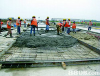
In this system of VDF Flooring or Vacuum Dewatered Flooring, concrete is poured
in place & vibrated with a poker vibrator especially to the sides of the panel
for floor thickness more than 100mm. Then surface vibration is done using double
beam screed vibrator running over the surface, supported on channel shuttering spaced
4.0 meters apart. The screed vibrator is run twice to achieve optimum compaction
& levelling. The vibrated surface is then levelled using a straight edge.
After this a system of lower mats & top mat is laid on the green concrete &
this is attached to a vacuum pump. This draws out surplus water if any. The concrete
is left to stiffen. When the base concrete has stiffened to the point when light
foot traffic leaves an imprint of about 3-6 mm, Floor Hardener, if specified,
is applied at this stage evenly at rate of between 3-5 Kg per sqm. ? Any bleed water
should now have evaporated, but the concrete should have a wet sheen.? ?The concrete
is then further compacted and levelled using Power Floater followed by finishing
as per the requirement using Power Trowel.
Vacuum processing improves compressive strength and how vacuum affect the top and
bottom part of the slab respectively. Note that after just seven days the compressive
strength value of vacuum dewatered concrete will be the same as that of normal concrete
after 28 days.
Proper Care
Production of a quality concrete slab requires proper techniques and adequate planning.
The following key areas have been identified as the most critical to achieving a
satisfactory result.
Subgrade- The subgrade must be properly compacted
and drained in order to give the bearing support assumed in design. Without support,
the slab has little chance of supporting design loads. Maximum deflection under
a fully loaded ready mix truck should be 13 mm.
Vapour Barriers- are normally provided to minimise
moisture transmission. The selection of vapour barrier is based on the
moisture sensitivity of the floor covering to be installed. Vapour barriers can
be placed directly beneath and in contact with the concrete slab, or a layer of
granular fill may be installed between the concrete and the barrier. Direct placement
of concrete on top of a vapour barrier can contribute to problems such as plastic
and drying shrinkage cracking and curling.
Admixtures- use of suitable admixture for enhancing
specific properties depending on the functionality should be carefully chosen and
decided. Testing should be performed to determine how the admixture(s) will affect
the properties of the concrete given the specified job materials, as well as the
anticipated conditions and construction procedures. Often, admixtures are used in
combination with one another. A second admixture can significantly affect the dosage
requirement of both admixtures. Preliminary tests are recommended to ensure the
optimum dosage of each admixture. Successful placements onsite will verify proper
workability, finishability and setting time. It is important to consult the manufacturer
for specific material handling, dosage and application instructions.
Synthetic Fibres- Synthetic fibres for use in concrete
floors increase the cohesiveness of concrete and should meet the requirements specified.
The most widely used synthetic fibres are polypropylene and nylon, although other
types are available. Fibres are generally available in both fibrillated and monofilament
forms. Structural macro-fibres (larger coarse fibres) can be used to provide equivalent
post-crack strength to conventional reinforcement depending on the specific fibre
dosage (see page 8 of this guide for further information). Synthetic macro fibres
can also be used to reduce plastic shrinkage cracks as well as minimizing drying
shrinkage cracks when used in a low shrinkage mix (0.04% @ 28 days or less). Synthetic
micro-fibres, polypropylene and nylon, are most widely used to reduce the formation
of plastic shrinkage cracks and to hold cracks tight.
Placing Sequence- In many cases, the most efficient
way to place concrete in large areas is in long alternating strips. Strip placements
allow superior access to the sections being placed and most suitable in case of
VDF.
Bleeding- Excessive bleeding is a major deterrent
to achieving quality slab surfaces always. Though in case of VDF this is taken care
of by the very process, care should be taken in respect of proper concrete mix proportioning,
the use of a well graded aggregate, controlled vibration and slump, concrete temperature
control help. Collected bleed water should be removed before the start of finishing
operations or the application of dry shake surface hardeners or toppings.
Evaporation-Rapid evaporation and moisture loss can
result in plastic shrinkage cracking in the slab surface. This undesirable appearance
can be minimized or prevented by dampening the subgrade, cooling water and aggregates,
using windbreaks or sunshades, eliminating vapour barriers, using fog sprays, and/or
treating the concrete with a monomolecular film just after floating.
Typical Application Areas
- Warehouses, Store houses, Factories
- Roads, Sports Courts
- Cellars, Parking Areas
- Manufacturing Areas,
- As the base floor for special finish Floorings
Benefits & Features
- Increased Compressive strength by up to 60%
- Reduced Cement consumption by 40% as no cement is required separately
for finishing.
- Increased Abrasion resistance by @ 60%
- Reduced Shrinkage.
- Minimizing dusting, crack formation
- Uniform homogeneous floor with High flatness accuracy
- Increased wear resistance
- Earlier utilization and Reduced maintenance cost
- Lower water permeability due to increased density.
- Minimizes dry shrinkage and plastic shrinkage
- Controlled working Cycle
- Earlier start of finishing operation
- Fewer forms faster reutilization
- High early strength minimizes damage on newly cast floors
VDF- Step by Step
- Clean the location free from dust and other unwanted material. If required floor
wash to be carried out to ensure proper bonding between the concrete and the surface
to receive the concrete.
- Provide a suitable type of Vapour Barrier if required as per specification.
-
Mark the area longitudinally so as to place the end channels at a spacing not to
exceed 4 meters.
- Provide Reinforcement (Mesh or In-situ fabrication) with
provision for dowel bars. These dowel bars are required as alternate panels are
cast.
- Place end channels at about 4 meters apart, well anchored avoiding any
movement.
- Place Concrete as per the design mix preferably through a transit
mixer.
- Spread and Compact properly using needle vibrators.
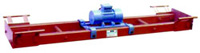
- Run the
screed vibrator spanned across the two end channels twice (Figure 3). Double Beam
Screed Vibrator- used for levelling as well as compaction of green concrete it consists
of high quality steel bar (4.2meter) with of 250 spacing MM in between. Our special
water protective vibrator motor is mounted in the centre which produces 1830 N centrifugal
force which is most ideal for compaction of green concrete. These vibrators are
also available in different sizes from 2 meter to 5.5 meter.
-
|
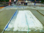
Spread the Vacuum mat system. The vacuum is applied through porous mats connected
to a vacuum pump. The mats are placed on fine filter pads which are provided to
prevent the removal of cement together with the water. The mats can be placed on
the concrete immediately after screeding, and can also be incorporated in the inside
faces of vertical forms. The vacuum applied is normally of the magnitude 0.08 Mpa.
This vacuum reduces the water content usually by about 20%. The reduction
is greater near to the mat. Care should be taken proper trained staff operates and
applies the correct pressure.It is normally observed that whenever a
|
 |
vacuum pressure is applied, it compress the concrete sufficiently so that it is
necessary to place extra concrete to compensate. Usually the slab gets compressed
about 2 percent. This means that for a 6-inch-thick slab the screeds must be set
high by 1/8 inch.
Suction Mat & Top Mat, which is the most important part of the vacuum de watering
system. Suction mat is also known as the Filter Mat and comprises of a filter cloth
on a wire mesh. The filter mat ensures that the cement fines are not sucked at the
time of the vacuum process. These are available in size of 35 sq
meters total. The top mat is only placed on top of the filter and work for sealing
the vacuum.
- Extract excess water from concrete using vacuum pump-Vacuum
pump, Filter mat and Top mat are important components in the VDF process. They help
to extract the excess water as described above from the concrete matrix. The excess
water thus sucked is diverted ensuring not to get remixed with the concrete that
is already placed.
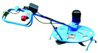
- Allow concrete to initially set. Start finishing operation
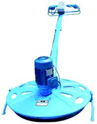
using mechanical floaters. (Figure 6)- Power Trowel that is surface finishing equipment
that polishes the surface after floating operation and 3 to 4 passes are required
for giving fine finish to the floor. Power Floater, which is surface grinding equipment
powered by 3 H.P. Electric motor through gear box with floating RPM of
130. The Power Floater offered by us grinds the surface to make it wear resistance.
-
Edges to be finished manually or using smaller discs.
- Avoid damage to the
finished floor.
- Cure the concrete
- Cut the groves as specified and
fill the sealant.
- Protect the concrete till the adjacent panel is cast.

|
 |
The Operation
- In order to obtain a high quality concrete floor using this method,
it is essential to follow the various operations in the correct sequence. Initially,
poker vibration is essential, especially at the panel edges. This results in proper
compaction of the concrete and hence elimination of voids and entrapped air.
- Poker vibration never really gives a levelled surface. It is therefore
essential to combine this vibration with surface vibration (screeding), in order
to obtain a vibrated concrete with a levelled surface. Two passes with surface vibrator
are normally recommended.
|
- The Surface Vibrator is guided by two men, standing on either
side of the panel. Vacuum dewatering process removes surplus water always present
in the concrete. This is done using the Vacuum Equipment comprising of Suction Mat
Top Cover, Filter pads and Vacuum Pump. The process starts immediately after surface
vibration.
- Filter pads are placed on the fresh concrete leaving about 4 inches
of fresh concrete exposed on all sides. The Top Cover is then placed on the filter
pads and rolled out till it covers the strips of exposed concrete on all sides.
The Top Cover is then connected to the vacuum pump through a suction hose and the
pump is started.
- Vacuum is immediately created between the filter pads and the
top cover. Atmospheric pressure compresses the concrete and the surplus water is
squeezed out. This process lowers the water content in the concrete by 15-25%.
- The dewatering operation takes approximately 1.5 - 2 minutes per
centimetre thickness of the floor. The dewatered concrete is compacted and dried
to such an extent that it is possible to walk on it without leaving any foot prints.
This is the indication of concrete being properly dewatered and ready for finishing.
- The finishing operations - Floating & Trowelling take place
right after dewatering. Floating operation is done with Floating disc. This ensures
after mixing of sand & cement particles, further compaction and closing the
pores on the surface. Floating operation generates skid-free finish.
- Trowelling is done with Trowelling blades in order to further
improve the wear resistance, minimize dusting and obtain smoother finish. Repeated
passes with disc and blades improve the wear resistance substantially.
|
|
Factors affecting VDF
Fresh concrete contains a system of water filled channels and the application of
a vacuum to the fresh concrete surface results in water being extracted from a certain
depth of the concrete, especially near to the top surface. This water is referred
to as ‘water of workability’. The final water / cement ratio at the
surface is thus reduced and as this ratio largely controls the strength of the concrete
and a higher strength will be obtained. However it must be noted that some of the
water extracted leaves voids and as such the theoretical advantage of removing the
water may not be fully achieved in practice. It is also observed in practice that
if Vacuum Dewatering process is applied over a 25 minute period, it can reduce the
water content by 20% but is only really effective at depths of 100 – 150mm.
Although there are several advantages using Vacuum Dewatering process on concrete
floors resulting in increased strengths, increased density and assists increase
abrasion resistance, there are some factors that affect the the entire process.
However, while designing an effective VDF, following factors are to be considered.
- The withdrawal of water produces settlement of the concrete, possibly
up to 3%. This can be topped up with the application of a dry shake but with little
bleed water at the surface there is a risk of subsequent delamination.
- In practice the VDF process produces voids in the concrete and
it has been found that with the same water / cement ratio, ordinary concrete has
been found to have a somewhat higher strength than VDF concrete.
- VDF concrete stiffens very quickly. This is acceptable in cold
climatic conditions but leaves the window of workability very short in hotter climates.
- Some of the finer materials are removed with the VDF process and
fine sands and cement contents of greater than 350 Kg / m should be avoided.
Groove Cutting
Concrete expands and contracts constantly with changes in the temperature, the moisture
content of the air and due to drying of cement which results in shrinkage.? The
movements result in stress that can cause cracks in the concrete and destabilization
of the base.
Uncontrolled cracking can cause an uneven surface, which is subject to increased
wear over time and water seepage, which can damage the substrate. ?Though cracking
is almost impossible to prevent, it can be controlled.? The use of specific types
of control joints helps accommodate the movement of the concrete and avoid long-term
damage.
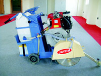
Groove Cutting is cutting the laid concrete providing grooves of required size within
48 hours of placing of the concrete to form bays of 4Mtrs X 4Mtrs using heavy duty
cutting machine with diamond cutting wheel and filling of the grooves with appropriate
sealant.?
Making Grooves is one such method to insert contraction joints into slabs to guide
cracks along a predetermined line. The purpose of the Groove Cutting is to weaken
the slab along the approved line so that the slab cracks there instead of somewhere
else. In order to be effective, the contraction joint must be at least one quarter
as deep as the slab is thick.
??In case of heavy load traffic, a Load Transfer mechanism is used. Load transfer
devices prevent the cement slabs from shifting under heavy loads. Shifting can cause
uneven slabs and breakdown in the joints. Dowels, load plates, or slots can be embedded
into the concrete to act as load transfer devices. These devices are laid perpendicular
to the construction joint, extending into both slabs across the joint. Their purpose
is to distribute the load evenly between slabs thereby protecting the concrete along
the joints.
Joint Sealants
Joint Fillers and Sealants are hard, semi-rigid materials typically used to fill
the construction joints in concrete floors. The joint filler transfers the load
of heavy wheeled traffic across the joint, protecting the joint edges from damage.
Joint sealants are flexible materials that expand and contract along with the concrete.
Their main purpose is to prevent water, other liquids, and debris from entering
the joint. They can also improve the appearance of a floor. Most sealants are available
in colours and can make the joints “disappear”. Sealants are one or
two-component polyurethanes and should not be used on floors that will receive heavy
traffic or loads because sealants will not support and protect the joint edges.
|
Dry shake floor hardeners come in mineral aggregate and metallic varieties. The
selection of a dry shake hardener is dependent on the specific solution intended
for the particular application. Floor hardeners provide a dense, tough surface capable
of withstanding the abrasion and impact loading seen by floor slabs in a wide range
of commercial, industrial and manufacturing facilities. Dry shake hardeners provide
2 to 8 times the abrasion resistance of plain, cured concrete. Most manufacturers
offer hardeners in a range of colours.
|
 |
Special Finishes
Metallic floor hardeners are formulated with graded, non-oxidizing or oxidizing
metallic aggregate in a high strength cementitious binder. Mineral hardeners contain
a mixture of well graded, non-metallic aggregates, plasticizer and cement binder.
Both are recommended for use in either interior or exterior applications where a
hard, long wearing, heavy duty floor is required. Metallic hardeners should not
be applied to concrete with intentionally added chloride.
Non-oxidizing metallic and mineral aggregates come in a light reflective version
designed to increase reflectivity to improve lighting levels. In combination with
providing increased abrasion resistance, this type of dry shake floor hardener can
boost reflectivity in excess of 60%. Benefits can include lower electrical requirements
and fewer light fixtures resulting in significant cost savings.
The use of embedded mineral or metallic hardeners is usually intended for industrial
floors exposed to moderate or heavy traffic. In some cases, floor hardeners are
applied where impact resistance is required. The manufacturer’s recommendations
should be followed along with the procedures.
Accordingly, dry shake floor hardeners should be embedded near the top surface of
the slab to obtain the required surface hardness, toughness and impact resistance.
It is recommended that the total air content of normal weight concrete should not
exceed 3% except when service conditions expose the concrete to freeze/thaw cycling
and the slab is not hard-trowel finished. Consult the manufacturer and ACI for specific
installation guidelines since these vary slightly between metallic and mineral hardeners
due to differences in their properties. In general, it is advised that good construction
practices be followed. This includes obtaining flat and level surfaces and joints,
using proposed mix proportions when installing test panels or placements and making
any required adjustments at that time. A concrete mix design review should be conducted
prior to installation of a dry shake floor hardener with all appropriate parties
present. Issues such as air content, use of blended cements, concrete admixtures,
and placing and finishing techniques should be discussed and agreed upon before
the project begins.