CASE STUDY - 3
Classical Case of Collapse Of A New Retaining Wall And Its Rehabilitation
Introduction
There could be several reasons for collapse of structures and many means of rehabilitating them. The main reasons for collapse can be attributed to any one or combinations of design deficiency, construction deficiency, poor quality of materials, and deterioration of concrete and lack of communication. Investigations to be carried out depend on the type and extent of failure. It is necessary to appropriately diagnose the reasons for failure to propose a judicious rehabilitation schemes.
Newly built retaining walls of length 120m on eastern and western side and 80m on northern side with concrete block masonry constructed over them as compound walls formed the enclosures of a MNC factory building in Bangalore. The cantilever retaining wall on eastern side was L shaped, retaining earth to a height of 5.0 - 5.5m above the NGL. Similar retaining wall was constructed on the western side but with shallower height of earth retained varying from 3m to 4m. Northern side retaining wall was of counterfort type.
It was shocking to see that on a heavy rainy day, the L shaped Cantilever Retaining Wall (LCRW) on eastern side had collapsed for a length of about 15m in the middle portion (Fig - 3.1), but luckily without causing any loss or damage to life.
This paper deals with the details of investigations carried out to identify the reasons for the collapse and the alternative strengthening measures suggested and adopted to stabilize the retaining walls.
Factory side Earth side
Fig - 3.1 : Longitudinal Views of Overturned Retaining Wall
Investigations Carried Out
As a first step, the physical inspection of the collapsed retaining wall as well as the other retaining walls existing at site was carefully carried out and site conditions were observed. Procurement of GFC structural drawings from the contractor and their verification with ‘as - built’ condition at site formed the next part of investigation. Proof checking of the structural drawings provided by the structural consultant was absolutely necessary. It was also decided to assess the existing strength of hardened concrete of the retaining wall to compare with that assumed strength in design. The results of all these investigations would contribute in unfolding the reasons for collapse.
Physical inspection
A thorough physical inspection of the failed retaining wall and of the entire site was made by the investigation team consisting of the consultant’s, contractor’s and owner’s representatives and the following observations were recorded:
-
The LCRW on the eastern side had overturned in the mid portion from the earth side to factory side disturbing the retained earth (Fig - 3.1) on the outside of the factory.
-
Removal of earth was being carried out to make way for dismantling the collapsed retaining wall.
-
Most of the portion of the masonry of about 1m height which was existing over the failed retaining wall had collapsed.
-
At about mid length, the retaining wall had sheared off, exposing the reinforcement in the stem. The lapped horizontal reinforcement had snapped. At this section total failure had taken place. (Fig - 3.2 and 3.3)
-
And on both sides of this failed section, number of diagonal cracks had developed due to torsion. (Fig - 3.4).
-
The stem of the retaining wall showed stepped cross–section with stepped face towards the inside of the factory and vertical face towards the outside where the earth was retained. Dismantling of collapsed retaining wall had commenced exposing the reinforcement in the stem at about 2.0-2.5m from the top.
-
Examination of exposed reinforcement in the stem of LCRW showed that the main reinforcement was placed on the stepped face towards the factory whereas the earth was retained on the face outside the factory, which was surprising.
-
There were no weep holes provided throughout the length of this part of the retaining wall.
-
Retaining walls on the other sides were found to be intact. Few weep holes were seen on the northern side counterfort retaining wall.
-
The natural land on the east side outside of the factory was sloping substantially from upper east side towards the factory forcing the rain water on this area to flow towards the retaining wall.
 |
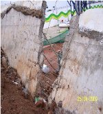 |
Fig - 3.2 : Closer View of Failed Retaining Wall Fig - 3.3 : Sheared Stem of the Retaining Wall
Fig - 3.4 : Damaged Portions of Stem
Drawings Procured from Contractor
It was learnt that the structural drawings pertaining to construction of the LCRW under consideration were supplied by the structural consultant to the owner of the project. These were transferred to the contractor by the client’s site engineer. Copies of these drawings giving the structural details as executed at site were procured from the contractor. The cross section of LCRW obtained from one of the structural drawings is shown in Fig - 3.5. As the reinforcement in the stem was already exposed, it was easy to verify both the concrete section and reinforcement provided with that present in the procured structural drawings.
In addition, drawings pertaining to contour map of the factory site and master plan with contours were made available by the contractor.
Observations
Examinations of structural drawing revealed the following:
-
The earth retained seemed to have changed from the factory side (with stepped stem) of the retaining wall (indicated as inside) to outside the factory side (with vertical face of stem) (Ref. Fig - 3.5).
-
However, the main reinforcement indicated in the drawing remained towards inside face of stem i.e., original face towards which the earth was expected to be retained.
-
Contour maps confirmed that the earth was sloping from east to west i.e. towards the retaining wall.
Fig - 3.5 : Cross Section of L-Type Retaining Wall as in Procured Structural Drawing
Core Test Rresults
Though initially it was thought to conduct NDT tests to assess the quality and compressive strength of concrete, this was not felt necessary as concrete core tests were already conducted by a reputed agency and the results of the same were made available to the present consultant.
From the core test results, neglecting such cores which contained reinforcement, the compressive strength of concrete in the stem was assessed as 25N/mm2 (based on the acceptance criteria for compressive strength for cores as per IS:456 2000), which was same as that adopted in the design (as mentioned in structural drawing).
Inferences Drawn from Observations
-
LCRW was designed by the structural consultant such that the earth retained was towards the stepped face of the stem i.e., towards the inside of the factory (Fig - 3.5). Correspondingly, the placement of main reinforcement was on the inside face in the drawing which was also found to have been employed in the field.
-
The site observations revealed that the earth was retained outside the factory building with the vertical face of stem being towards the earth but the main reinforcement was located on the opposite face of the stem.
-
After few discussions it came to light that as per site condition, the clients site Engineer had changed the face of earth retained from 'inside' to 'outside' in the structural drawing issued by the structural designer without bothering about any consequential change in the structural features (reinforcement details in particular).
-
The main vertical reinforcement in the stem of the LCRW is therefore placed not on the face towards the earth retained but happens to be on the rear face of the stem which essentially means wrong placement of main tension reinforcement and becomes ineffective to a large extent under load.
-
This indicates severe lack of communication between the personnel of design group, site engineer (owner's side) and contractor.
-
Due to heavy rain the previous day, all the water has flown towards the retaining wall thereby saturating the soil.
Therefore it is necessary to carry out the proof checking of structural designs for saturated soil condition in addition to natural soil condition.
Proof Checking of Structural Drawings
Proof checking of structural drawings of the LCRW was done using the data from ‘as-built’ conditions, core tests results, structural drawings provided and adopted at site and soil properties available. The structural designs were carried out for two conditions.
-
Lateral Earth pressure due to soil in natural condition
-
Lateral Earth pressure due to soil in saturated condition. Measured from NGL, the height of earth retained was confirmed as 5m and depth of foundations as 1.6m. The main design details of concrete section and main reinforcement required for the two states of soil are presented in Table - 3.1. The proof checking of design considering the actual earth face and actual reinforcement existing on tension face revealed the following:
- For the condition of Earth pressure due to normal soil, thickness of stem and main reinforcement provided fall short by 25% & 108%. In addition, thickness of base slab (heel only) provided falls short by 50% (however, reinforcement available is adequate when calculated for required higher depth of base slab (Table – 3.1) and hence, strengthening is required.
- For earth pressure due to saturated soil condition, when compared to normal soil condition, the quantities of concrete section and main reinforcement required in both stem and heel slab are substantially high (Table - 3.1) and obviously strengthening is required.
Table -3.1 : Comparison of Main Design Details between Required and Existing Quantities
Reasons for Failure of L-Type Cantilever Retaining Wall
The failure of retaining wall based on physical observations, study of the structural drawings and the redesign of the cantilever retaining wall for the condition as constructed at site may be attributed to the following reasons.
-
As per the existing condition at site as provided and as constructed, the main vertical reinforcement in the stem of LCRW is provided on the opposite face of the earth retained (Fig - 3.5). Hence, the existing main vertical reinforcement provided on the earth face is totally inadequate to resist the lateral earth pressure in normal condition itself.
-
The existing width and depth of base slab and available tension reinforcement are grossly inadequate to resist the lateral earth pressure due to fully saturated soil condition. Hence, the failure.
-
Lack of communication: From Sec. (3.3) above, it can be seen that the additional factor leading to failure is the lack of communication between the client’s site engineer, design group and the construction group.
How the Failure could have been avoide
-
Taking into consideration the realistic site condition, the structural drawing should have been studied by the clients in consultation with PMC or original structural consultants before releasing the drawing for construction.
-
When once the earth retaining face is changed as per the structural drawings, the clients should have contacted the consultants for providing revised structural drawings.
-
As proposed in the original structural drawings weep holes should have been provided in the retaining wall which would have reduced the additional lateral pressure due to water.
-
The authorized engineer of the client had given site instructions through the structural drawings incorporating the revision in the levels of earth retained and indicating the change of earth retaining surface on the outer face of the retaining wall.
-
Unfortunately, as per revised earth surface, corresponding change in the main vertical reinforcement had not been indicated. (No engineering judgement has gone in before issuing the revised drawing).
-
A drain of sufficient capacity should have been provided on the outer periphery of the retaining wall to drain off the rain water flowing from upper region of the sloping land on the eastern side outside the factory, in the absence of weep holes.
Recommendations
Based on the physical observations made, information gathered from the original structural drawings and based on the results of the redesign of the LCRW, the following recommendations were made:
-
The stem of the failed portion (plus 5m on either side) of LCRW on the eastern side shall be totally demolished from south to north and reconstructed with new design details and existing base slab to be strengthened (Fig - 3.6).
-
Instead of building a retaining wall to resist the huge lateral earth pressure due to fully saturated condition of soil, a better solution would be to provide a drainage system to prevent flow of rain water towards open area of retaining wall. Then the LCRW can be strengthened for normal earth conditions.
-
The same original detailing has been adopted in the LCRW constructed on the southern side and part of northern side. Accordingly similar type of failure may occur any time. Hence, it is advised to strengthen these existing retaining walls as per requirement immediately.
-
The design and structural detailing of counter fort type retaining wall constructed on the northern side of the factory along the existing natural drain shall also be checked appropriately.
-
Weep holes shall be provided in the retaining wall depending on the requirements, at site.
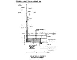 |
Fig - 3.6 : Strengthening of Base Slab and with New Construction of Stem
Strengthening Scheme Adopted
Of the two options of strengthening suggested, strengthening of stem as well as base slab from outside was recommended.
Following step-by-step procedure was provided to execute the strengthening scheme. The details are shown in Fig - 3.7.
Fig - 3.7 : Strengthening by Jacketing (by Concreting) of Existing Stem and Base Slab
and Anchoring of Base Slab to Rock
Strengthening of Base Slab
- Remove the existing soil above the base slab from inside upto the top of existing base slab.
- Clean the top surface by water jetting until the soil is completely removed and the concrete surface is exposed.
- Roughen the top surface of base slab, using wire brush and clean the dust by water jetting or air blasting.
- Drill holes of 25mm diameter from the top of base slab into the rock below the slab to a depth of 1.5m at a spacing of 1m in zigzag manner.
- Pour polyester resin grout completely into the drilled holes as per manufacturer’s specifications.
- Insert 20mm diameter rod into the hole right through the depth, such that 150mm is exposed above the top of the base slab.
- Steps (iv) to (vi) are meant for anchoring base slab to rock below
- Apply a coat of epoxy adhesive over the roughened surface of base slab to integrate new concrete with existing concrete.
- Provide leakproof shuttering for concreting above the base slab.
- Provide prefabricated reinforcement on to the base slab as per the detailing given in the drawing.
- Pour free flow / self compacting ready mix concrete of grade M25, as per the requirement.
- Cure well for a minimum period of 10 days.
- Continue this process over the entire length of base slab both for new construction of stem, as well as for strengthening of stem.
Strengthening of Stem by Jacketing
-
Remove the earth from outside completely upto the bottom of the base slab.
-
Clean the vertical surface of the stem by water jetting, such that the concrete surface is free from earth.
-
Roughen the surface of the stem by wire brushing and clean the dust by water jetting or air blasting
-
Provide shear connectors of 12mm diameter at a spacing of 1000mm c/c in zigzag manner.
-
Provide reinforcement as per the new design and tie with shear connectors such that they stand vertically to plumb.
-
Apply a coat of epoxy adhesive to bring about integral action between new and existing concrete.
-
Provide leakproof shuttering to the stem such that the cover is 25mm and pour ready mix concrete of M25 grade completely.
-
Remove shuttering after 24 hours and cure well for a minimum period of 10 days.
-
Continue this process to the entire length of retaining wall to be strengthened.
Conclusions
The reasons for the failure of the L-shaped cantilever retaining wall were attributed to the incorrect placement of the vertical reinforcement in the stem away from the earth surface which was mainly due to the lack of communication between the stake holders. Design details and drawings were provided for construction of new retaining wall in place of failed portion of retaining wall. Dismantling of the retaining wall in the distressed portion followed by reconstruction and strengthening measures for the remaining portion of the retaining wall were suggested and successfully executed. The strengthened L-shaped cantilever retaining walls was found to be stable and performing satisfactorily.
Overall Conclusions
All the three Case Studies of structural failure presented are due to human mistake / blunders. It may be due to lack of quality control during construction, errors in structural designs, wrong detailing going unnoticed by qualified Consultants and reputed contractors, awarding more contracts to incapable contractors, etc.All the three Case Studies of structural failure presented are due to human mistake / blunders. It may be due to lack of quality control during construction, errors in structural designs, wrong detailing going unnoticed by qualified Consultants and reputed contractors, awarding more contracts to incapable contractors, etc.
Hence, the lessons learnt from the above, is that it has become absolutely necessary to:
-
Implement appropriate measures of strict QA/QC at site.
-
Site Engineers and supervisors shall be trained and made known about the proper use and pros and cons of RMC.
-
Detailing of reinforcement shall be read, checked, rechecked and understood before fabrication at site. If any errors are noticed shall be brought to the notice of the Consulting Engineer immediately.
-
Peer review / proof checking of structural designs shall be made compulsory, irrespective of the original designer.
-
In the fast track construction, in the race to reach the target, many factors are ignored, in particular, curing of concrete, it shall be given due importance from the durability point of view.
References
- A comprehensive report on Core test Non Destructive Test and Retrofitting of Columns of a Multistoried Building under Construction, Whitefield, Bangalore, Vol. 1 and 2, 2006.
- Jagadish. R., Editor. -Structural Failure-Case Histories'. Oxford IBH Publishing Co. Pvt. Ltd., 1995.
- ACI Committee 364, 'Guide for Evaluation of Concrete Structures Prior to Rehabilitation', American Concrete Institute, 1999.
- Jagadish, R., Investigation report submitted to KSHIP, Bangalore
- Jagadish, R., Editor, 'Structural Failures - Case Histories', Oxford and IBH Publishing Co. Pvt. Ltd., 1995.
ABOUT THE AUTHOR
 |
Dr. Jagadish has been a teacher for over 35 years in both undergraduate and postgraduate courses and was formerly Professor and Chairman, Faculty of Engineering (Civil) at the University Visweswaraiah College of Engineering, Bangalore University, and Development Officer (2000-2002), Bangalore University. He has been in research for 30 years and has been a professional structural engineer for over 35 years.
He was till recently, Executive Director (Technical) of Srikar and Associates (P) Ltd, Bangalore and is currently Chief Consulting Engineer, M/s. Consultants Consortium, Bangalore.
|
Dr. Jagadish has designed and executed a large number of prestigious multi-storeyed buildings, industrial structures, commercial complexes, hotels, hospitals, educational institutions, indoor and outdoor stadia etc. He has also specialised in failure investigations and remedial construction and has evaluated and restored/rehabilitated/retrofitted over 100 buildings in distress.
He is a member of a large number of Indian and International professional institutions, societies and associations, and has presented over 150 papers in Indian and International journals, symposia and conferences.