INNOVATIVE PRECAST CONCRETE STRUCTURES AN INDIAN EXPERIENCE
Vasudev V Nori
Shirish Patel and Associates Consultants Private Limited (India)
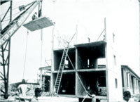
Fig-1.1.1: A view of the large panel construction for an apartment building.
ABSTRACT. This paper deals with the way in which efficient concrete structures have evolved in our firm during the last fifty years. For precast concrete structures to qualify as being efficient they should be cost effective, resulting in reduction in material consumption, easily buildable and needing little maintenance. For such an objective to be realised the designer needs to explore new structural forms and also needs to have an in depth appreciation of the impact of various stages construction and associated constraints. The designer needs to take into account problems of de-moulding, type of erection equipment that would be available, construction tolerances, and problems concerning tilting and erection. One of the structures described briefly is a combination of precast and cast in situ constructions which incidentally was also the recipient of one of the five “Most Outstanding Structure Award” at the XIIth FIP Congress held at Washington in 1994. Concrete bridges are often simply supported structures with bearings and expansion joints. Like elsewhere in the world much of the observed distress in these bridges emanates from expansion joints and bearings. This paper also deals with evolution of precast concrete bridges with monolithic piers which need very little maintenance. The structures described have proved to be to be both elegant, efficient and maintenance free compared to traditional cast-in-situ structures.
Dr Vasudev V Nori is the Chairman of Shirish Patel and Associates Consultants Private Limited. Founded in 1960 this is one of the oldest firm of Consulting Engineers in India
1 LARGE PANEL PREFABRICATION FOR RESEDENTIAL APARTMENTS
1.1 PETIT HALL
1.1.1 Introduction: Large-panel prefabrication in India began in Bombay (now Mumbai) almost 50 years ago with the design of a group of 27-storeyed residential buildings, of which three were built over the next few years. These buildings had traditional open foundations. The lowest 3 floors, used for parking and a podium, were cast in place. But the upper 24 residential floors were fully precast, using large-panel walls, hollow-core slabs, and box-shaped façade elements for window protection. In-situ concrete was used only in the vertical and horizontal joints.
At that time India had very strict import controls. The Contractors, who were also the developers and thus had control over both design and construction for the project, were unexpectedly lucky and got permission to import two tower cranes of 75 tonne-metre capacity (8 tonnes maximum hook load, 2.5 tonnes at 30m radius). They wanted to put these to use immediately and develop the technology for prefabricated housing construction.
Unfortunately, for this first project the plan and architectural dimensions had already been frozen before the decision was taken to use prefabrication. It meant that the 170 panels per floor would need to be of 103 different types. So panel repetitions were too few . But this was acceptable considering that a technology new to India would be developed.
Fig-1.1.1: A view of the large panel construction for an apartment building. Because this was the designers’ as well as the contractors’ first experience of reinforced
concrete prefabrication, it was decided to build and load test, on a different site some kilometres away, a full-scale 3-storeyed mock-up, using wall and slab panels similar to those intended for the final construction. Vertical joints between wall panels in the mock-up were differently configured to test a variety of possible joint details.
1.1.2 Mock-up Testing
 |
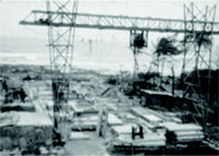
The mock-up consisted of a cast in-situ foundation in three strip footings, surmounted by a precast floor consisting of 8 slab units as shown (Fig.1.1.2). Each was 200 mm thick with longitudinal hollows. Above were three parallel load-bearing precast walls, each 8m long overall, comprising either 3 or 5 elements, spaced 3.9m apart. These carried a further three identical levels of precast floor slab units. Above the last of these were three parallel cast in- situ parapet walls, aligning with the precast walls below. Above these, at right angles and straddling across all three parapet walls were several pairs of transverse parallel steel I- beams.
|
Each pair supported six hydraulic jacks above, which stressed vertical prestressing cables running on either side of the precast walls below.The cables all had dead anchors against similar transverse parallel I-beams placed in slots in the cast in-situ strip foundations below.
Fig-1.1.2: Full scale Mock up and testing by prestresing cables
The forces in the vertical prestressing cables exerted the weight of 20 floors above, and could be varied to simulate the bending moment due to wind. The shear force due to wind was provided by two horizontal prestressing cables at the level of the uppermost slab. Instrumentation was carried out with the support of the Indian Institute of Technology Bombay and consisted of measuring horizontal and vertical deflections at each of the four slab levels on both sides of the building, as well as strains in the walls. Crack widths in different joints were also measured. A detailed report of the load test has been published elsewhere.i Essentially the findings were that against vertical forces deflections were slightly less than expected, suggesting that the modulus of elasticity was a little better than the assumed value of 18,000 MPa. However, against horizontal shear the movement of the precast walls, while being consistent with that of a monolithic wall, suggested a modulus of elasticity reduced by about 30%. In other words, against horizontal shear the walls behaved as if the in-situ joints between panels introduced a degree of softness in the rigidity of the walls. But the most surprising behaviour was in the application of moments. Vertical forces applied above different panels did not disperse along the length of each wall as one expects in monolithic behaviour (even one with a reduced modulus of elasticity).
1.1.3 Construction
 |
An earlier thought of using 225mm thick hollow walls was given up while the mockup was under construction. It was decided to use 200mm thick exterior walls and 175mm thick interior walls throughout. The extra thickness of external walls was considered necessary to accommodate the joint waterproofing arrangements. |
 |
This was an age when the designers took full responsibility for the entire project, from design of the structure to design of the forms, advising the contractors on the casting and handling arrangements, and supervision of construction. Accordingly, tower cranes were positioned at the centre of each building. The sizes of precast panels was determined by the crane capacity of 75 tm. The farthest panels, almost 30m away, could thus be not more than 2.5 tonnes in weight, while nearer panels could be larger, up to the maximum hook capacity of 8 tonnes. |
 |
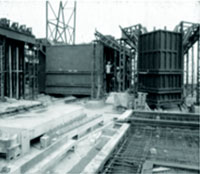
With panel sizes determined, steel battery moulds hanging from elevated rails placed a little over storey height were designed for the 175mm thick interior walls. The 200mm thick exterior walls had ground level flat tilting moulds, to which external finishes could be applied soon after casting. Slab moulds were all flat. The entire yard was served by a single overhead gantry crane, also designed by the project designers. |
Fig-1.1.3: View of the casting yard, battery moulds, external wall panel moulds.
The 200mm thick slab panels called for longitudinal hollows 125mm high x 345 wide, spaced 420mm apart. A variety of ways of forming the hollows was thought of and experimented with the arrangement finally adopted (Fig. 1.1.3) has two vertical plates forming the sides of each hollow. Forming the bottom and top of the hollow are two horizontal top and bottom plates slightly bent at the edges and touching the side plates. The side plates are held apart by a pantograph mechanism. Once the concrete has set, the pantograph mechanism can be operated to draw the side plates towards the centre of the hollow. The upper plate then falls into the hollow, and the lower plate can be lifted into the hollow. Since the centre of the hollow is wider than the top and bottom plates, and deeper than the side plates, all four collapse towards the centre and can then be simultaneously and easily extracted.
Overall, the Contractors’ experience of the project was positive. They found they were able to complete four floors in a month, in contrast to the one floor a month possible with traditional in-situ construction. Unfortunately, this made no difference to the completion time for the project, since those who had pre-purchased flats in the building had a payment schedule linked to the progress of construction. The purchasers found themselves unable to produce the instalments required at the speed at which the project was proceeding. Hence the contractors found themselves finishing 4 floors in a month, and then waiting 3 months for the money to come in before starting up again. However, they found that ultimately the cost proved comparable to that of an entirely in-situ construction. The quality was distinctly superior. And a much quicker pace of construction was possible provided financing was not a constraint.
1.2 ANDHERI HOUSING SCHEME
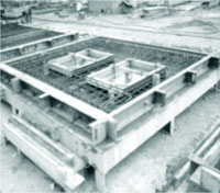
1.2.1 Introduction:It was decided to adopt this technology for a subsequent project. Designed ab-initio for prefabrication, this comprised a number of G+7 buildings, with a high degree of repetition of panels. These buildings had box-unit bathrooms, ribbed floor slabs, 175mm thick solid internal wall panels and 200mm thick hollow external walls. Materials were both scarce and costly in those years, and the hollows were for economy in material consumption. The 200mm thickness of external walls was the minimum considered necessary to manage all the complexities needed to ensure a watertight vertical joint. The box-unit bathrooms, finished in the casting yard with all tiling, sanitary fixtures and plumbing, proved particularly successful in terms of quality delivered when compared with their in-situ equivalents. While the second of these two successful projects was under construction, the construction company that had executed both these unfortunately collapsed and went out of business. The technology developed was not taken up by any other construction or manufacturing company.
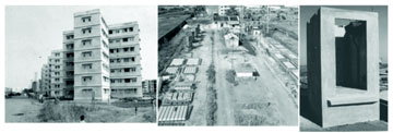 |
Fig-1.2.1: Andheri Housing Scheme, casting yard and box unit bathrooms
1.2.2 Joint Details
What is critical in the design of large-panel precast wall and slab systems is the detailing of the vertical and horizontal joints, particularly the external joints, so that they provide the requisite structural strength and at the same time do not leak. The designers’ and contractors’ people had visited and seen large panel prefabrication in several countries in Europe before taking up the project. The British joint details were thought to be not sturdy enough, and the East European practice of heavier reinforcement in the vertical and horizontal joints was adopted instead. Wall panels had nominal temperature reinforcement on each face, with the major vertical reinforcement running through the vertical joints in the hole formed by overlapping U-bars projecting from either side. Wall panels also had U-bars projecting above and below, overlapping with U-bars from the upper and lower wall panels, and overlapping also with U-bars from the slab on either side. Horizontal reinforcement was threaded through all four sets of U-bars from the two walls and two slabs meeting at a horizontal joint. Fig. 1.2.3 shows the joint details adopted.
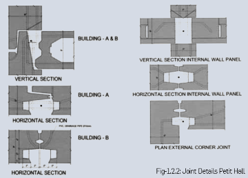 |
Fig-1.2.2: Joint Details Petit Hall
The design was carried out before the Ronan Point disaster of 16 May 1968. By that time one of the three prefabricated buildings had already been completed, and the second was under way. Since it is the external walls that would be most sensitive to being blown out, it was decided immediately that the horizontal steel in all external horizontal joints should be welded wherever possible.
Joint details were complex in regard to the arrangements needed to ensure the water tightness of each joint - for example, they called for overlapping GI sheet strips in the vertical joints. These had to be correctly installed during construction. There was no possibility of replacing them later. So while the detail worked well if properly executed, it took only a few instances of improper execution to produce some leaking joints. A few leaks were enough to give the entire system a bad name. The current situation is that on the extreme end external façade wall all joints, both vertical and horizontal, have been solidly filled and are performing well. On other walls the joints are visible and are kept watertight by the application of an elastomeric sealant.
1.2.3 Improved Joint Details
Fig-1.2.3: Improved joint Details - Andheri Housing Scheme.
On subsequent projects, the joint details departed from the earlier details in two major respects: First (used on the second and third housing projects), external wall panels had a projecting lower lip that extended outside the principal plane of the wall panel and thus hung over and fully covered the horizontal joints. These were therefore completely protected and received neither direct rainfall nor dripping from the wall above. The overhanging lips have remained in remarkably good condition and are performing well (Fig. 1.2.3) over 40 years after the building was finished.
2. INDUSTRIAL STRUCTURES
2.1 FABRICATION SHOP AT BANGALORE
2.1.1 Introduction: The structure described here is the first of many workshop buildings that was constructed for manufacturing hydraulic excavators. The fabrication shop which is
60 m wide and 160 m long was constructed during the years 1974-75. The manufacturing process required that overhead electric cranes in three end bays each 20 m ( one at southern
end and two at the northern) to have a East-West travel. In the middle 5 bays each of 20 m the overhead electric cranes were to have a North-South travel. Almost all the bays were
required to be served additionally by semi portal cranes of smaller capacity. The building design was such that it should permit future extensions on any of the sides. The client’s
initial requirement was a column grid of 20 m x 10 m. The client had also decided that the execution would be undertaken by its subsidiary construction wing which had wide
experience in precast concrete construction for factory buildings. Looking at various options a 20 m square grid proved to be the best choice. Instead of having two crane girders (one for
the main overhead electric crane and the other for semi-portal crane) with two brackets it was possible to have a single truss that would carry both the travelling cranes. This also gave full
flexibility in the sense that crane girders could be reoriented by 90 degrees so that overhead cranes could be realigned to travel North-South even in end bays. The building was planned
on a modular grid of 2.5 m. The entire building is in precast concrete except for columns and foundations which were cast in place. The building is made up of five precast concrete
elements:
- Pretensioned hypar shells 2.5 m wide spanning 20 m.
- Prestressed bow-string truss spanning 20 m.
- Pretressed gantry girders spanning 20 m
- Reinforced concrete wind girders spanning 20 m
- Reinforced concrete wall panels 2.5 m wide and 14.7 m high
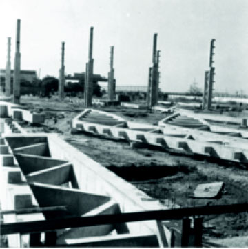
2.1.2 Pretensioned Hypar Shells: This happened to be first large scale application of Hyperbolic paraboloid shells in India. This shape is ideally suited or pre-tensioning as straight wires are located with maximum eccentricity at mid span and at mid depth at the ends. The shell thickness is 50 mm typically with a slight thickening at the edges. The surface could be easily formed using masonry moulds. And the form is such that the precast shell unit separates itself from the mould smoothly on de-tensioning. The joints between adjoining units occur at ridges thus eliminating the possibility of rain water ingress. Longitudinal curvature of the shell has one beneficial structural action that results in substantial reduction in transverse bending moments as compared to those that would occur in a cylindrical shell with identical cross section. The very first shell that was cast was load tested successfully. 192 such shells were cast using two moulds. Since the contract provided for 2% breakages, which in fact did not occur, one additional shell was cast and tested to failure. All tests were carried out under the guidance of Indian Institute of Science so that results would be available for researchers. The shell units are used in North-light form of construction. The concrete consumption of the roof unit is just 0.073 m3/m2 of covered area confirming the efficacy of the form.
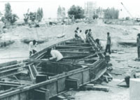
2.1.3 Bow-string Roof Girders: These are 20 m span tied arch girders that carry the Hyperbolic paraboloid shells. Because of North light configuration one end of the roof unit rests on the chord and the other end resting on the bottom chord. These are cast in horizontal position using simple forms adjacent to columns as can be seen in Figure 2.1.1. The bottom chord is post tensioned. The concrete consumption of the roof girder is about 0.019 m3/m2.
Fig-2.1.1: View of precast shell unit being towed into position(left) View showing cast in situ columns , precast crane girders and roof girders (right)
2.1.4 Gantry Girders: These are 20 m span precast concrete trusses. The top chord supports the main overhead electric crane and the bottom chord supports semi portal cranes. The depth of the crane girder is 2.3 m which is governed by the difference in rail levels of the upper and the lower cranes. The trusses are cast horizontally using simple formwork adjacent to columns as can be seen in Figure 2.1.1. The weight of the crane girders is 33 t.
2.1.5 Wall Panels: The wall panels are 2.5 m wide and 14.7 m are 50 mm thick two 450 mm deep ribs at either end. The bottom 3.6 m is louvered as can be seen in Figure 2. The louvers themselves are 50 mm thick reinforced concrete elements placed in the side formwork of the wall panels. Daylight can be seen through the joints between the wall panels which are open. But the rain water does not enter because of diagonal ribbing provided on the sides during casting. The external finish for the wall panels consists of cut beer bottles which were placed immediately after casting the wall panels as can be seen in Figure 2.1.3. This provided a fluted surface so that wind drive rain would be directed vertically downward. Glass being glossy in nature prevents growth of moss on the facade. Air gap between the bottle and concrete provides added insulation. This finish required no maintenance even after 36 years.
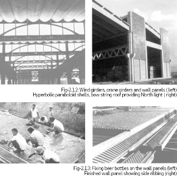 |
Fig-2.1.3: Fixing beer bottles on the wall panels (left) Finished wall panel showing side ribbing (right)
2.1.6 Wind girders: These are L shaped elements in reinforced concrete spanning 20 m providing horizontal support for resisting wind loads.
2.1.7 Columns: The columns are cruciform in shape and are cast in situ. Foundations are conventional open foundations. The lengths of various precast elements were calculated by combining the tolerances of cast-in-situ columns with those of precast elements by the root mean square method.
2.1.8 Future extensions: In 1989 the building was extended by 20 m on the northern end. The wall panels and wind girders were dismantled and reused without any difficulties. This confirmed that precast concrete factory buildings can be designed to give virtually the same flexibility as factory buildings in structural steel.
2.2. WORKSHOP BUILDING AT HYDERABAD
2.2.1 Introduction: The clients invited bids for construction of a workshop building covering an area of 13200 m2 in structural steel with a north light roof. Bidders were given an option of offering an alternative design which conformed to their technical requirements such as span configuration loads due to electrically operated overhead travelling cranes, vertical and horizontal clearances, natural lighting, foundation depths, safe bearing capacity and future extensions. The building is 160 m long and 78 m wide. Columns are spaced at 12 m centres in the longitudinal direction and at 30 m, 24 m and 24 m in the transverse direction. Client’s North light solution leads to gutters along the valley line running across the width of the building with internal down takes along the columns leading to internal storm water drains. This was the solution that was adopted in all other existing workshop buildings in this complex. Unless maintained scrupulously the roof gutters tend to overflow during heavy rainfall. Also internal walkways were specified for maintenance and cleaning of north-light glazing from inside. These walkways are a source of obstruction reducing the natural daylight substantially apart from being unsightly.
2.2.2 Salient features of proposed design: The proposed design in precast concrete offered a solution with strip lights which provide excellent natural lighting as can be seen in Figure 2.2.1. The proposed alternative building is free of internal down rain water down takes and storm water drains. Except for foundations the building is in precast concrete assembled from of six basic elements:
1. Precast pretensioned purlins spanning 12 m
2. Precast pretensioned cladding runners spanning 12 m
3. Precast pretensioned gutters spanning 12 m
4. Precast post tensioned roof trusses spanning 30 m and 24 m
5. Precast post tensioned crane girders spanning 12 m
6. Precast reinforced concrete branched columns of heights 16.5 m and 13.5 m.
Fig-2.2.1: 30 m bay of completed workshop building with strip lighting
Precast concrete ensures a high quality of concrete since all casting is done at ground level. The member thicknesses could be reduced to minimum values which results in a very light construction. Concrete/masonry moulds can be used which results in saving in the cost of formwork.
 |
Precast concrete industrial structures are economical, elegant and relatively maintenance free. This technique offers designers an opportunity to explore new efficient structural forms which are not practical for cast in situ construction Designing such structures in precast concrete entails much more engineering effort compared to that required for design of steel structures. On the other hand precast concrete have less consumption of concrete and elegant at the same time. |
Concrete consumption in the roof is just 0.052 m3/m2 of covered area. Completed in 1983 many of the precast elements described below were first time applications both for the designer and for the contractor.
Fig-2.2.2: Precasting of funicular truss in progress(left) Tilting and lifting arrangement of funicular truss (right)
2.2.3 Precast pretensioned purlins, cladding runners and gutters: These are L shaped members 400 mm deep with a 250 mm wide flange spanning 12 m. The elements are only 50 mm thick. The purlins are cast in 60 m long pretensioning beds using masonry moulds as fixed shutters. The cladding runners are similar to purlins except that the flange is wider for resisting horizontal loads due to wind effects.
2.2.4 Precast pretensioned purlins, gutters: Also spanning 12 m. gutters are U shaped members 50 mm thick with flanges water combining the function of end purlins and rain water drainage. The cross section is such that the entire rain water is drained at the gable ends. No internal rainwater town takes were required.
2.2.5 Precast post tensioned funicular roof trusses: Most commonly used structural configuration of precast concrete trusses have been inspired from similar forms commonly used for structural steel trusses. The configuration of the truss adopted on this project is such that for uniform loads the entire bending moment is resisted by axial forces in the compression chord and the tension chord. The verticals and diagonals are subjected to very nominal forces and can be made as slender as the construction permits. Concrete consumption is remarkably low. These are easily cast on ground and formwork required is indeed very simple as can be seen in Figure 5. Tilting these trusses into vertical position and lifting them in position however needs to be carefully planned and detailed. It is important that all such details should be provided by the designer. In all 45 trusses were cast and erected without a single breakage.
 |
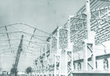 |
Fig-2.2.3: Branched columns, funicular trusses cast flat on ground(left) Erections of 24 m span funicular trusses in progress.
2.2.6 Precast post tensioned crane girders: These are post tensioned I girders spanning 12 m requiring to support electrically operated overhead cranes of various. Prestressed concrete girders are not only cheaper than structural steel crane girders but are also much superior as compared to structural steel girders from fatigue considerations.
2.2.7 Precast reinforced concrete branched columns: These are reinforced concrete columns with a height of 16.5 m for 30 bay and 13.5 m for 24 m bay. The larger column height for 30 m may was specified by the client to meet the operational requirement. Individual legs of double branched columns are connected by diagonal bracing as can be seen in Figure 6. Thus all the bending moments are resisted mainly by axial forces thus resulting
Since these columns are cast in horizontal position the formwork is quite simple and inexpensive. Columns are tilted about weaker axis which requires a careful consideration. In all 60 such columns were cast and erected without a single breakage.
3. BRIDGES IN PRECAST CONCRETE WITH MONOLITHIC JOINTS
3.1 Introduction: Simply supported girders resting on bearings are still very popular. The main reason for their popularity is that these structures are simple to design and to execute. The substructure design is also greatly simplified because of determinate nature of the structure. On the other hand most of the distress observed in bridges constructed during the last fifty years emanates from the expansion joints and bearings. Unsatisfactory performance of expansion joints results in ingress of rain water through the joints and causing damage both to the structure and to the bearings. It became necessary to detail these joints so that adequate space is available for maintenance and replacement. During earthquakes it has been found that spans get dislodged from bearings at times. Indian Road Congress Codes require that positive measures such as restrainers be provided for bridge structures in Zone IV and Zone V so that the deck does not get dislodged during earthquakes.
Elimination of bearings improves the structural performance during earthquakes. Finally integral form of construction will require much lesser inspection and maintenance efforts.
3.2 Issues specific to the design of integral form of construction: The main difference between the traditional structures with simply supported spans on piers and integral form of construction is due to considerable interaction between the substructure and the superstructure. Some of the effects are beneficial but the others one not. In the traditional structures if one overestimates the shrinkage creep and temperature it’s impact on the cost is restricted to the cost of bearings and expansion joints. The dimensions of the superstructure and substructure remain unaffected. But with integral form of construction one has to make a more careful assessment of creep, shrinkage and temperature effects. One aspect critical for the design of integral form of construction is a need for better understanding of thermal response of concrete structures. Because of high thermal resistance concrete structures do not heat up quickly like steel structures. There is a considerable time lag between the peak ambient temperatures and peak concrete temperatures. This is one area in which much has to be learnt by making observations on the existing bridges. Bridges piers which are monolithic have to necessarily slender compared to those supporting simply supported spans. Change in the structural system as the construction progresses needs to be carefully assessed. If construction joints are located judiciously the effect of creep on change in the structural system can be greatly minimised.
3.3 Road bridges with precast prestressed girders and monolithic piers: Monolithic piers with precast prestresed girders presents a few additional problems but certainly feasible. Some fourteen road over bridges were built a few years ago for crossing railway lines, one of which can be seen in Figure 10. Without exception all bridges are integral form of construction. For integral form of construction to be feasible, piers have to be necessarily slender even if heavily reinforced.
The width of the carriage way of most of the bridges is 11.70 m catering for two lanes of vehicular traffic plus 1.5m wide foot paths on either side. The carriage way is supported on five precast post tensioned girders with 1 m depth for 15 m spans and a 240mm thick reinforced concrete deck slab which is cast-in-situ. At track crossings where 20m spans required the girder depth is 1.20 m. Continuity of the bridges in the longitudinal direction is achieved by providing non tensioned reinforcement in the deck slab. Piers are varying in thickness from 500 mm to 600 mm. Piers rest on pile caps with 4 cast-in-situ bored concrete piles of 1 m diameter. Monolithic connections between piers and the deck requires detailing of reinforcement, bearing in mind sequence of operations tolerances etc. Twin piers are provided at all expansion joints spaced about 75 m apart. Additional design efforts are needed in analysing designing and detailing such structures which are certainly more complex than the conventional bridge structures with simply supported span on bearings. But additional costs incurred in engineering such structures are compensated since not only these bridges are economical but also in long run such bridges will require little maintenance and are expected to perform better during earthquakes.
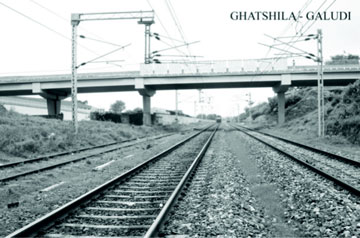 |
Fig-3.1: Road bridge with monolithic piers with precast post-tensioned girders
3.2 Full span precast concrete viaduct for light rail transport system with monolithic piers:
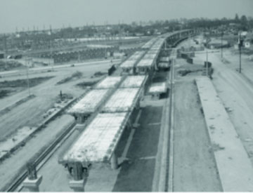
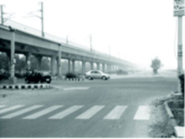
A 6.5 km long viaduct was constructed about 7 years ago for carrying two rail tracks spaced transversely 4.1 m centres. There are no bearings for the entire length of the viaduct. A 61m module with a span configuration of 13.5 m + 16.5 m + 16.5 m + 13.5 m appeared to be the best choice. This configuration met with the requirements of various road crossings and could be used typically for the entire length so as to obtain maximum repetition. The cross section consists of two 1.2 m deep post tensioned precast voided trapezoidal girders. These are precast full span adjacent to the site and erected in position using a gantry straddling across the viaduct as can be seen in Figure 3.2. Corbels are provided for individual circular piers so that precast girders could directly rest on the substructure without any additional temporary supports. The cross diaphragms were then cast providing a monolithic connection. Longitudinal continuity is achieved by stressing cap cables. Effects of creep results in introduction of support moments into the structure. The height of the rail varied between 7.0 m to 9.0 m above ground level. At a few locations the rail level was 10.30 m above ground level. The structure is founded on open foundations resting on medium sand. A couple of images of this viaduct can be seen in Figure 3.3.
 |
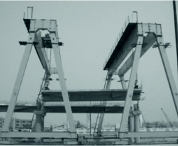 |
Fig 3.2: Full span precast post tensioned girders for light rail transport (left) Erection of post tensioned girders with gantry (right)
There were two locations where the viaduct had to span 36 m. In these locations the parapet was integrated into the superstructure deck which then assumed H shape. The deck was temporarily supported on neoprene bearings so that much of shrinkage and creep effects could be taken care of before making the connection monolithic.
3.3 Elevated Road cum Metro Project over Ajmer Road at Jaipur : This recently completed flyover is about 5.75 km in length running through Jaipur. About 1.75 kM of the flyover is a double deck construction supported on single central pier. Double track metro rail runs on the upper deck and a four lane road traffic runs on the lower deck. Span configuration varies to suit the alignment with maximum spans of 37 m reducing to 25 m on sharp curves. One of the challenges was to evolve a solution that would permit the same erection machinery to be used for construction of both the decks. The foundations consist of cast in situ bored piles of diameters varying from 1.00 m to 1.50 m .This is perhaps first application of double deck flyover in India. Delhi Metro Rail Corporation (DMRC) was keen to integrate their standard solutions for the super structure into the double deck portion of the flyover. The solution finally chosen was precast segmental construction for both the decks. Amongst other benefits span lengths could be increased to 37 m which was an important consideration considering cost of pile foundations. The metro rail would be supported on standard DMRC segmental box design used in Delhi and the lower deck would be supported on precast segmental spine girder. The dimensions and weights were comparable to that of the standard DMRC segmental box and therefore same erection machine could be used for construction of both the decks. Precast cantilever arms would then be attached to the spine girder by prestressing and cast-in-situ stitch concrete. A brief layout of the entire project is shown in Fig 3.4. The flyover begins with ramps leading to a two lane flyover for about 2.95 kM.
 |
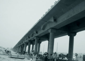 |
Fig - 3.3: Monolithic connection achieved by casting diaphragm over piers (left) completed structure in operation (right)
At this point the flyover is joined by another ramp to cater for three lanes of road traffic. For next 680m length, the flyover is widened to cater for five lanes of road traffic. At Sodala Junction, metro rail coming from Ramnagar side joins the flyover and one lane from flyover gets diverted towards ‘Hawa sadak’. For the next 1.54 kM this is a double deck flyover supporting 4-lane road at 1st level and double track metro at 2nd level. Beyond civil line station just before existing road over bridge (Ajmer Pulia) the metro alignment gets separated from the flyover. The four lane flyover gets split into two flyovers each of two lanes merging gradually into the widening of existing road over bridge at Ajmer Pulia.
Fig-3.4: Layout of elevated road cum metro project at Jaipur.
- The superstructure spans are typically 37 m on straight alignment
- reducing to 25 m on sharp curves. The spans are simply supported resting on PTFE bearings. The flyover is supported on a single central pier for most of the locations. The piers supporting metro structure are circular in shape with a diameter of 1.8 m. The lower part of the pier is 2.0 m wide and 2.6 m long (along the direction of traffic). At some locations because of severe constraints imposed by site conditions the upper deck had to be supported on portal frames. Figure 3.5 shows a cross section showing some typical details.
Fig-3.5: Typical cross section of double deck flyover
Weight of 3m wide precast cantilever arms is maximum 17.5 t. The cantilever arms are integrated into the spine girder by post-tensioning and cast in place stitch concrete. Since pier sizes could not be increased the viaduct was supported on portal frames (Fig 3.6) at these locations
In the remaining part of the flyover without metro rail running above, as the construction proceeded there were several revisions in the alignment due to availability of space, constraints due to existing heavy traffic at some junctions. This included relocation of ramps integrating into the four lane flyover which required 2 lane flyover to be supported on cantilever arms as shown in fig 3.7
At one location the four lane flyover had to be enlarged to accommodate one more lanes for connecting a future two lane flyover. This meant that a five lane carriageway had to be Thus the spine girder had to support two lanes on one side and three lanes on the other. Since spine girder cross sections could not be alteterd spans were restricted to a maximum of 25 m. A typical cross section of a five lane flyover is shown in Fig 3.8.
Fig 3.8: 5-Lane Flyover
Mid-span section In the last stretch the four lane flyover had to bifurcated and gradually integrated for widening an existing road over bridge (Ajmer Pulia) crossing railway lines without affecting the existing road or rail traffic.
The following photographs (Fig 3.9 to 3.12) shows the flyover as the construction proceeded.
Fig-3.9: Metro lines viaduct joins the four lane flyover
Fig 3.10: View before erection of cantilever arms.
Fig-3.11: View with cantilever arms in place
Fig-3.12: Metro viaduct separates from the flyover which gradually merges with widened Ajmer Pulia road over bridge.
4. ECC Administration building in Chennai: This is an usually shaper five storey building that was completed in two stages. The owner who also happened to be the Contractor preferred use of precast concrete to the maximum extent possible. Typical floor is a two way grid with precast concrete waffles and cast-in-situ concrete. The external façade including the mullions were in precast concrete. The five storey office building is supported by prestressed hollow inverted pyramids support:
In the first stage three storeys were completed and occupied on 1983. Additional two storeys were completed in 1990. The configuration of typical floor is derived four 21.6 m squares placed in line of one of the diagonals 15.273 m apart. The central square 10.8 m x 10.8 m houses the elevators, staircases and rest rooms. The typical floor is a waffle slab supported on the mullions along the external facade and a central core 2.5 m x 2.5 m each with four L shaped columns. The architectural feature as conceived by Mr Piloo Mody (Mody and The tests confirmed that the structure would behave generally as predicted by preliminary calculations. The entire building rests on four well foundations.
Fig-4.1: ECC Administration Building - Recipient of one of the five Most Outstanding
Structure Award - XII FIP Congress Washington - 1994 (left) Typical cross section showing hollow pyramids (right)
ACKNOWLEDGEMENTS:
 |
Mr Shirish B Patel (Chairman Emeritus) and Mr P H Srinivasachar (Director Technical, Retired) were the lead engineers for the Petit Hall and Andheri Housing Projects. Messrs Shah Constructions were the contractors for this project. The author gratefully acknowledges the encouragement, confidence and support of Larsen and Toubro Limited, Engineering Construction Corporation (L&T), Bharat Heavy Electricals (Hyderabad), Michigan Engineers Private Limited, Konkan Railway Corporation Limited, Delhi Metro Rail Corporation Limited, Afcons Infrastructure Limited, ITD-ITD Cem JV, The author is equally indebted to his colleagues for their participation in the projects described above. |