Museum Architecture-Laudable and Impeccable
Canadian Museum for Human Rights, Winnipeg, Canada
The Canadian Museum for Human Rights (CMHR) is a first new national museum in Canada located in Winnipeg at The Forks site at the confluence of the Red and Assiniboine rivers.
The architectural design for the CMHR was selected from an international competition that included 62 submissions from 21 countries. Ar. Antoine Predock from Mexico's winning design draws inspiration from the natural scenery and open spaces of Canada. Later it was initiated in 2003 by CanWest founder Israel (Izzy) Asper is to be the largest human rights institution and education centre in the world.
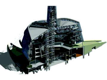
The CMHR is generally composed of four base 'Roots' radiating out from a central Great Hall, Garden of Reflection beneath a suspended Mountain, Cloud and Tower of Hope. The 50m-tall Hall of Hope atrium at the back of the building cuts into the Mountain and Roots like a canyon and houses circulation ramps.
W-360 Sections
The Mountain consists of a seemingly randomly stacked array of five stone-clad closed forms of irregular shape suspended 18m above ground level. Initially conceived in reinforced walls, eccentricity of stone cladding and unconventional vertical and horizontal load paths necessitated a change to structural steel framing.
Structural steel W-sections combine with corner circular hollow sections to form primary diagrid wall trusses within each two-storey form wall. Significant floor openings added complexity to the buckling restraint of diagrid wall truss compression members, requiring heavy W-360 column sections in some locations. Composite steel beams and slabs frame the Mountain floors by clear spanning between the diagrid wall trusses. Steel bracing beams and cover plates are added where diaphragm floor forces overstress concrete slabs.
Diagrid wall trusses span significant unsupported distances between concrete wall and steel column supports. The locations and angles of the diagonal and vertical elements within the diagrid wall trusses are positioned around wall openings to provide direct load paths down to supports. The diagonals also transfer lateral loads down the building with floor diaphragms distributing those loads across to supporting walls.
Mega Shore
Parametric sensitivity analyses were conducted to assess the effects of changes in temperature, concrete slab and wall cracking, construction sequencing and staging and connection fixities. Optimizing the diagrid wall truss member locations, designs and connections with consideration to these parameters is complicated by the redistributive nature of the stacked diagrids. Steel connections are designed by Walters Inc. with utilization of their four-dimensional design and modelling capabilities to rationalize the mountain connection nodes.
 |
The lower Mountain form cantilevers 16m over part of the Garden of Reflection. The massive supported weight of stone cladding, heavily loaded exhibition and plant floors, Upper Mountain, cloud roof and the Tower of Hope require this form to be super elevated at Diagrid wall trusses of stacked mountain forms erection to ensure flat floors in the final condition. Extreme loads also require six 500mm x 100mm solid steel plates to be built up to form a solid 500x600 steel diagrid member. The design and construction of this cantilever form proved to be the most challenging aspect of the project and the successful release of the mega shores was a celebrated project milestone.
Dove Wings
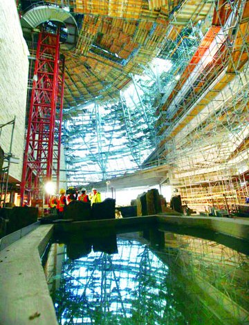
The glazed Cloud encapsulates the large central atrium allowing natural light to flood the museum offices and the Garden of Reflection. A primary structural framing geometry incorporates the curvature of the Cloud including the folding Cloud "Dove Wings". Raking built-up hollow steel columns span over 30m from the Roots up to the Cloud roof and support a series of 610mm-diameter hollow circular steel pipes curving around the Cloud perimeter at varying radii. Balcony-like partial perimeter office floors encircle the atrium at three levels and act as diaphragms to provide lateral stability to the raking columns.
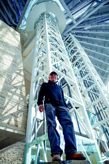
Steel framing also allows light into the Tower of Hope and practically unobstructed panoramic views. The underlying geometry consists of two overlapping cones discretised into faceted shards of layered glazed panels.
Other Structural Features
A two-directional, long spanning, steel truss support system provides column-free space for the dark void of the Great Hall below and supports the Tower of Hope elevator hoist-way and spiral stair above. In its central location, the Garden of Reflection is adjacent to all four Roots, three building cores and the Hall of Hope, and floats between these structural components on sliding bearings to prevent the attraction of significant compatibility forces.
Up to 25m long-span steel pony trusses are located within the glowing backlit alabaster stone clad balustrades of the circulation ramps that link the museum exhibition spaces and fly through the Hall of Hope atrium.
Design Excellence
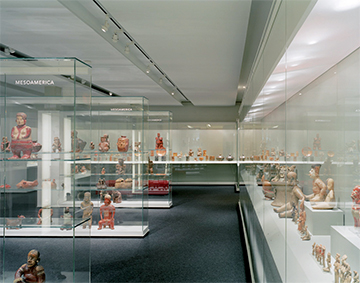
After 18 months and three levels of increasingly detailed submissions, the contemporary design of internationally renowned architect Antoine Predock was selected over those of 61 other firms from 12 countries. Entrance welcomes with 'tree roots' travelling through nearly 47,000 square feet of exhibit space and 2,300 ft of ramps. The average floor to ceiling height of each level is 17 ft mirroring the sense of vastness and openness in landscape. Garden of Contemplation with its still water pools and the Tower of Hope, a 328 foot high glass structure overlooking the Winnipeg prairie horizon.
Client Visualization
Traditionally, project teams require clients to interpret their 3D buildings from our 2D documents (e.g., plans, sections, elevations, renderings, and construction schedules). On the CMHR project, the project team sat with the client to review the museum in 3D, with live walk-through and renderings produced from vantage points of their choice. To help the client visualize and evaluate their options, the team even revised major structural components, such as curtain walls, right in front of their eyes.
 |
The VDC model provided the project team with an opportunity to break down the building into small components around which the team could plan construction sequencing and activities. In self performing the concrete work, PCL needed to install a large quantity of concrete shoring beams which diagonally supported the inside of the concrete walls and tied back to the floor slab. The location of these super-studs could not conflict with the structural steel to be installed later. PCL overlaid its 3D concrete wall shoring model on the 3D structural steel model produced by Walters Inc., and then adjusted the super-stud locations in the model to reduce potential conflicts in the field.
Virtual Model and Documentation
The unconventional architectural form of the CMHR meant that hand sketches or traditional 2D AutoCAD could not be rationalized into a 3D model. Instead, the team started with a 3D model, set datum points and planes for the geometry, created hand sketches to determine the construction make up and then added the digital information to the model.
Preconstruction Planning During the preconstruction planning phase, the project team embarked on extensive reviews of the VDC models to identify and address potential design issues or clash detection, prior to starting construction. Early clash detection presented a business advantage to the client, consultants and contractors, by saving the time and money associated with unnecessary rework.
The construction project marks the first time a national museum in Canada has been built with financial contributions from federal, provincial and municipal levels of government in addition to significant contributions from the private sector.
Contributions from the Province of Manitoba ($38.8 million) and the City of Winnipeg ($16 million) have been received, as well as the first three private sector installments from The Friends of CMHR ($67.2 million). In addition, land was donated by the City of Winnipeg and The Forks Renewal Corporation with an estimated market value of $4.9 million based on an independent valuation. The value was recorded in other comprehensive income in 2009-2010.
 |
Increased capital funding requirements were a key challenge in the Museum's first year. This increase was a result of more accurate costing through the design development process, construction inflation in Manitoba since the project was estimated at $265 million in 2006, and because the building was environmentally redesigned to meet LEED Silver environmental certification requirements. The Museum completed an extensive value engineering exercise to confirm the final $310 million project budget which includes the building and the inaugural exhibitions.
Risk Tolerance
A complex and large scale capital project presents a wide range of risks that need to be carefully managed including the risk of delay and cost overruns. The architectural design for the Museum building is extremely complex. A project team including CMHR staff executives, design architects, consultants and the construction manager has been established to reduce the likelihood of costly changes in design or additions or deletions to the work as the construction project proceeds. A design-assist procurement process is being used that, unlike traditionally bid projects, involves subcontractors during the design development and construction document stages of the project to provide valuable input into the design, planning, scheduling, budgeting (including the identification of cost-saving measures) and tendering a focused team effort towards delivery of the project. This approach has been used successfully with structural, mechanical and electrical trades and with the exterior glazed facade supplier.
 |
At this stage of construction with 95% of costs tendered and locked in the largest remaining risk relates to change orders due to unknown conditions encountered during construction. The use of the team approach and the design-assist process which involved the major trades from an early stage of design and construction is expected to greatly reduce this risk.
Construction Challenges
Capitalizing on its in-house VDC capabilities, PCL self-performed the CMHR's cast-in-place structure. The design incorporated exposed to view, sloped, battered and curved concrete walls as well as a free standing concrete wall with large openings. In addition, information from the model was used to design formwork and to fabricate panels to meet the CMHR's specific requirements, geometrically and dimensionally. Using VDC models for construction coordination paid big dividends.
Global Procurement
A significant level of pre-construction planning and coordination was required between the consulting and construction teams in North America and the subcontractor who designed and manufactured the building's exterior glazed facade in Europe. The project team used the VDC model to clarify information in the 2D drawings, which improved project efficiency by reducing the amount of time spent on data exchange and improving the accuracy of the information being shared.
Real-Time Collaboration
The project team overcame logistical challenges, such as bandwidth and server storage, by establishing a stable work platform in a virtual domain. By implementing remote desktop protocols during virtual meetings, team members were able to view, mark up, and take control of the model. Among the many benefits of the real-time collaboration were reduced travel time and costs, as well as improved communication and project coordination, thanks to increased meeting efficiency and expedited decision-making.
It was so comprehensive that, long before final documents were complete, the project team was able to simulate building performance, evaluating the impact of wind and smoke flow, as well as structural loading and construction sequencing.
High Tech Tools
To visualize, manage and document the project, team adopted new technology (e.g., tablets, 3D mice, rapid prototyping or 3D printing, holograms and motion-capture technology) that even a few years ago was largely unknown. The consulting team, which originally supported AutoCAD and three or four other programs as its primary production tools, adopted 24 software platforms to provide the vast range of data and input required for the CMHR. Likewise, PCL expanded its AutoCAD software suite to include a range of 3D modeling platforms by Autodesk.
References:
https://humanrights.ca/
http://uwinnipeg.ca/csrg/docs/CMHR_Annual_Report_2010-2011.pdf
http://www.pcl.com/Services-that-Deliver/Industry-Leadership/Leadership-Articles/Documents/CMHR-A-Case-Study-With-A-Difference.pdf
https://umanitoba.ca/research/media/ResearchLIFE_Winter_2014.pdf
http://www.predock.com/CMHR/CMHR.html