Causes of Distress and Deterioration of Concrete
Introduction
a. General: Once the evaluation phase has been completed for a structure, the next step is to establish the cause or causes for the damage that has been detected. Since many of the symptoms may be caused by more than one mechanism acting upon the concrete, it is necessary to have an understanding of the basic underlying causes of damage and deterioration. This chapter presents infor- mation on the common causes of problems in concrete. These causes are shown in Table 3-1. Items shown in the table are discussed in the subsequent sections of this chapter with the following given for each: (1) brief dis- cussion of the basic mechanism; (2) description of the most typical symptoms, both those that would be observed during a visual examination and those that would be seen during a laboratory evaluation; and (3) recommendations for preventing further damage to new or replacement concrete. The last section of the chapter presents a logi- cal method for relating the symptoms or observations to the various causes.
b. Approach to evaluation: Deterioration of concrete is an extremely complex subject. It would be simplistic to suggest that it will be possible to identify a specific, single cause of deterioration for every symptom detected during an evaluation of a structure. In most cases, thedamage detected will be the result of more than one mechanism. For example, corrosion of reinforcing steel may open cracks that allow moisture greater access to the interior of the concrete. This moisture could lead to additional damage by freezing and thawing. In spite of the complexity of several causes working simultaneously, given a basic understanding of the various damage- causing mechanisms, it should be possible, in most cases, to determine the primary cause or causes of the damage seen on a particular structure and to make intelligent choices concerning selection of repair materials and methods.
Causes of Distress and Deterioration
Table 3-1 Causes of Distress and Deterioration of Concrete
| Accidental Loadings |
| Chemical Reactions |
| Acid attack |
Aggressive-water attack
|
Alkali-carbonate rock reaction
|
Alkali-silica reaction
|
Miscellaneous chemical attack
|
Sulfate attack
|
Construction Errors
|
Corrosion of Embedded Metals
|
Design Errors
|
Inadequate structural design
|
Poor design details
|
Erosion
|
Abrasion
|
Cavitation
|
Freezing and Thawing
|
Settlement and Movement
|
| Shrinkage |
| Plastic |
Drying
|
Temperature Changes
|
Internally generated
|
| Externally generated |
| Fire |
| Weathering |
a. Accidental loadings.
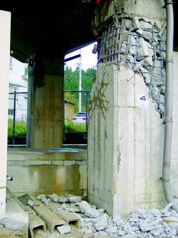
- Mechanism: Accidental loadings may be charac- terized as short-duration, one-time events such as the impact of a barge against a lock wall or an earthquake.These loadings can generate stresses higher than thestrength of the concrete, resulting in localized or general failure. Determination of whether accidental loading caused damage to the concrete will require knowledge of the events preceding discovery of the damage. Usually, damage caused by accidental loading will be easy to diagnose.
- Symptoms: Visual examination will usually show spalling or cracking of concrete which has been subjected to accidental loadings.Laboratory analysis is generally not necessary.
- Prevention: Accidental loadings by their very nature cannot be prevented. Minimizing the effects of some occurrences by following proper design procedures (an example is the design for earthquakes) or by proper attention to detailing (wall armor in areas of likely impact) will reduce the impacts of accidental loadings.
b. Chemical reactions.
This category includes sev- eral specific causes of deterioration that exhibit a wide variety of symptoms. In general, deleterious chemical reactions may be classified as those that occur as the result of external chemicals attacking the concrete (acid attack, aggressive water attack, miscellaneous chemical attack, and sulfate attack) or those that occur as a result of internal chemical reactions between the constituents of the concrete (alkali-silica and alkali-carbonate rock reac- tions). Each of these chemical reactions is described below.
(1) Acid attack.
 |
- Mechanism: Portland-cement concrete is a highly alkaline material and is not very resistant to attack by acids. The deterioration of concrete by acids is primarily the result of a reaction between the acid and the products of the hydration of cement. Calcium silicate hydrate may be attacked if highly concentrated acid exists in the envir- onment of the concrete structures. In most cases, the chemical reaction results in the formation of water-soluble calcium compounds that are then leached away. In the case of sulfuric acid attack, additional or accelerated deterioration results because the calcium sulfate formed may affect the concrete by the sulfate attack mechanism (Section 3-2b(6)). If the acid is able to reach the rein- forcing steel through cracks or pores in the concrete, corrosion of the reinforcing steel will result and will cause further deterioration of the concrete (ACI 201.2R).
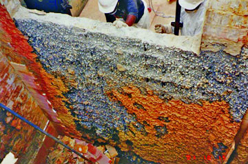
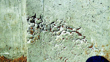
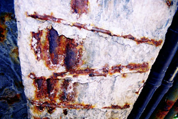
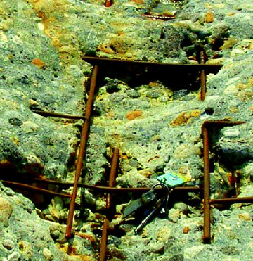
- Symptoms: Visual examination will show disin- tegration of the concrete evidenced by loss of cement paste and aggregate from the matrix (Figure 2-13). If reinforcing steel has been reached by the acid, rust staining, cracking, and spalling may be present.If the nature of the solution in which the deteriorating concrete is located is unknown, laboratory analysis can be used to identify the specific acid involved.
- Prevention: A dense concrete with a low water-cement ratio (w/c) may provide an acceptable degree of protection against a mild acid attack. Portland- cement concrete, because of its composition, is unable to withstand attack by highly acidic solutions for long periods of time. Under such conditions, an appropriate surface coating or treatment may be necessary. ACI Committee 515 has extensive recommendations for such coatings (ACI 515.1R).
 |
A dense concrete with a low water-cement ratio (w/c) may provide an acceptable degree of protection against a mild acid attack. Portlandcement concrete, because of its composition, is unable to withstand attack by highly acidic solutions for long periods of time.
(2) Aggressive-water attack.
- Mechanism: Some waters have been reported to have extremely low concentrations of dissolved minerals. These soft or aggressive waters will leach calcium from cement paste or aggregates. This phenomenon has been infrequently reported in the United States. From the few cases that have been reported, there are indications that this attack takes place very slowly. For an aggressive- water attack to have a serious effect on hydraulic struc- tures, the attack must occur in flowing water. This keeps a constant supply of aggressive water in contact with the concrete and washes away aggregate particles that become loosened as a result of leaching of the paste (Holland, Husbands, Buck, and Wong 1980).
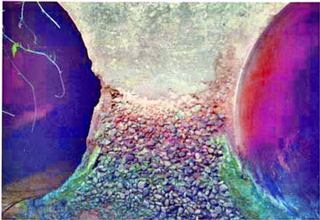
- Symptoms: Visual examination will show con- crete surfaces that are very rough in areas where the paste has been leached (Figure 2-12). Sand grains may be present on the surface of the concrete, making it resemble a coarse sandpaper. If the aggregate is susceptible to leaching, holes where the coarse aggregate has been dis- solved will be evident. Water samples from structures where aggressive-water attack is suspected may be ana- lyzed to calculate the Langlier Index, which is a measure of the aggressiveness of the water (Langlier 1936).
- Prevention: The aggressive nature of water at the site of a structure can be determined before con- struction or during a major rehabilitation. Additionally, the water-quality evaluation at many structures can be expanded to monitor the aggressiveness of water at the structure. If there are indications that the water is aggres- sive or is becoming aggressive, areas susceptible to high flows may be coated with a nonportland-cement-based coating.
(3) Alkali-carbonate rock reaction.
- Mechanism: Certain carbonate rock aggregates have been reactive in concrete. The results of these reac- tions have been characterized as ranging from beneficial to destructive. The destructive category is apparently limited to reactions with impure dolomitic aggregates and are a result of either dedolomitization or rim-silicification reactions. The mechanism of alkali-carbonate rock reac- tion is covered in detail in EM 1110-2-2000.
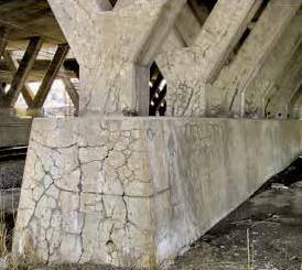
- Symptoms: Visual examinationof those reac- tions that are serious enough to disrupt the concrete in a structure will generally show map or pattern cracking and a general appearance which indicates that the concrete is swelling (Figure 2-7). A distinguishing feature which differentiates alkali-carbonate rock reaction from alkali-silica reaction is the lack of silica gel exudations at cracks (ACI 201.2R). Petrographic examination in accor- dance with ASTM C 295 (CRD-C 127) may be used to confirm the presence of alkali-carbonate rock reaction.
- Prevention: In general, the best prevention is to avoid using aggregates that are or suspected of being reactive. Appendix E of EM 1110-2-2000 prescribes procedures for testing rocks for reactivity and for mini- mizing effects when reactive aggregates must be used.
 |
(4) Alkali-silica reaction.
- Mechanism: Some aggregates containing silica that is soluble in highly alkaline solutions may react to form a solid nonexpansive calciumalkali-silica complex or an alkali-silica complex which can imbibe considerable amounts of water and then expand, disrupting the concrete Additional details may be found in EM 1110-2-2000.
- Symptoms: Visual examination of those concrete structures that are affected will generally show map or pattern cracking and a general appearance that indicates that the concrete is swelling (Figure 2-6). Petrographic examination may be used to confirm the presence of alkali-silica reaction.
- Prevention: In general, the best prevention is to avoid using aggregates that are known or suspected to be reactive or to use a cement containing less than 0.60 percent alkalies (percent Na20 + (0.658) percent K20). Appendix D of EM 1110-2-2000 prescribes proce- dures for testing aggregates for reactivity and for mini- mizing the effects when reactive aggregates must be used.
(5) Miscellaneous chemical attack.
- Mechanism: Concrete will resist chemical attack to varying degrees, depending upon the exact nature of the chemical. ACI 515.1R includes an extensive listing of the resistance of concrete to various chemicals. To pro- duce significant attack on concrete, most chemicals must be in solution that is above some minimum concentration. Concrete is seldom attacked by solid dry chemicals. Also, for maximum effect, the chemical solution needs to be circulated in contact with the concrete. Concrete sub- jected to aggressive solutions under positive differential pressure is particularly vulnerable. The pressure gradients tend to force the aggressive solutions into the matrix. If the low-pressure face of the concrete is exposed to evapo- ration, a concentration of salts tends to accumulate at that face, resulting in increased attack. In addition to the specific nature of the chemical involved, the degree to which concrete resists attack depends upon the tempera- ture of the aggressive solution, the w/c of the concrete, the type of cement used (in some circumstances), the degree of consolidation of the concrete, the permeability of the concrete, the degree of wetting and drying of the chemical on the concrete, and the extent of chemically induced corrosion of the reinforcing steel (ACI 201.1R).
- Symptoms: Visual examination of concrete which has been subjected to chemical attack will usually show surface disintegration and spalling and the opening of joints and cracks. There may also be swelling and general disruption of the concrete mass. Coarse aggregate particles are generally more inert than the cement paste matrix; therefore, aggregate particles may be seen as protruding from the matrix. Laboratory analysis may be required to identify the unknown chemicals which are causing the damage.
- Prevention: Typically, dense concretes with low w/c (maximum w/c = 0.40) provide the greatest resis- tance. The best known method of providing long-term resistance is to provide a suitable coating as outlined in ACI 515.1R.
(6) Sulfate attack.
 |
- Mechanism: Naturally occurring sulfates of sodium, potassium, calcium, or magnesium are sometimes found in soil or in solution in ground water adjacent to concrete structures. The sulfate ions in solution will attack the concrete. There are apparently two chemical reactions involved in sulfate attack on concrete. First, the sulfate reacts with free calcium hydroxide which is libera- ted during the hydration of the cement to form calcium sulfate (gypsum). Next, the gypsum combines with hydrated calcium aluminate to form calcium sulfoaluminate (ettringite). Both of these reactions result in an increase in volume. The second reaction is mainly responsible for most of the disruption caused by volume increase of the concrete (ACI 201.2R). In addition to the two chemical reactions, there may also be a purely physi- cal phenomenon in which the growth of crystals of sulfate salts disrupts the concrete.
- Symptoms: Visual examination will show map and pattern cracking as well as a general disintegration of the concrete (Figure 2-14). Laboratory analysis can verify the occurrence of the reactions described.
- Prevention: Protection against sulfate attack can generally be obtained by the following: Use of a dense, high-quality concrete with a low water-cement ratio; Use of either a Type V or a Type II cement, depending upon the anticipated severity of the exposure (EM 1110-2-2000); Use of a suitable pozzolan (some pozzolans, added as part of a blended cement or separately, have improved resistance, while others have hastened deterioration) If use of a pozzolan is anticipated, laboratory testing to verify the degree of improvement to be expected is recommended.
c. Construction errors.
Failure to follow specified procedures and good practice or outright carelessness may lead to a number of conditions that may be grouped together as construction errors. Typically, most of these errors do not lead directly to failure or deterioration of concrete. Instead, they enhance the adverse impacts of other mechanisms identified in this chapter. Each error will be briefly described below along with preventative methods. In general, the best preventive measure is a thorough knowledge of what these construction errors are plus an aggressive inspection program. It should be noted that errors of the type described in this section are equally as likely to occur during repair or rehabilitation projects as they are likely to occur during new construction.
(1) Adding water to concrete: Water is usually added to concrete in one or both of the following circumstances: First, water is added to the concrete in a delivery truck to increase slump and decrease emplacement effort. This practice will generally lead to concrete with lowered strength and reduced durability. As the w/c of the con- crete increases, the strength and durability will decrease. In the second case, water is commonly added during finishing of flatwork. This practice leads to scaling, craz- ing, and dusting of the concrete in service.
(2) Improper alignment of formwork: Improper alignment of the formwork will lead to discontinuities on the surface of the concrete. While these discontinuities are unsightly in all circumstances, their occurrence may be more critical in areas that are subjected to high- velocity flow of water, where cavitation-erosion may be induced, or in lock chambers where the "rubbing" sur- faces must be straight.
 |
 |
(3) Improper consolidation: Improper consolidation of concrete may result in a variety of defects, the most common being bugholes, honeycombing, and cold joints."Bugholes" are formed when small pockets of air or water are trapped against the forms. A change in the mixture to make it less "sticky" or the use of small vibrators worked near the form has been used to help eliminate bugholes. Honeycombing can be reduced by inserting the vibrator more frequently, inserting the vibrator as close as pos- sible to the form face without touching the form, and slower withdrawal of the vibrator. Obviously, any or all of these defects make it much easier for any damage-causing mechanism to initiate deterioration of the concrete. Frequently, a fear of "overconsolidation" is used to justify a lack of effort in consolidating concrete. Overconsolidation is usually defined as a situation in which the consolidation effort causes all of the coarse aggregate to settle to the bottom while the paste rises to the surface. If this situation occurs, it is reasonable to conclude that there is a problem of a poorly proportioned concrete rather than too much consolidation.
(4) Improper curing: Curing is probably the most abused aspect of the concrete construction process. Unless concrete is given adequate time to cure at a proper humidity and temperature, it will not develop the charac- teristics that are expected and that are necessary to pro- vide durability. Symptoms of improperly cured concrete can include various types of cracking and surface disinte- gration. In extreme cases where poor curing leads to failure to achieve anticipated concrete strengths, structural cracking may occur.
(5) Improper location of reinforcing steel: This section refers to reinforcing steel that is improperly located or is not adequately secured in the proper location. Either of these faults may lead to two general types of problems. First, the steel may not function structurally as intended, resulting in structural cracking or failure. A particularly prevalent example is the placement of welded wire mesh in floor slabs. In many cases, the mesh ends up on the bottom of the slab which will subsequently crack because the steel is not in the proper location. The second type of problem stemming from improperly located or tied reinforcing steel is one of durability. The tendency seems to be for the steel to end up near the surface of the concrete. As the concrete cover over the steel is reduced, it is much easier for corrosion to begin.
 |
 |
(6) Movement of formwork: Movement of form- work during the period while the concrete is going from a fluid to a rigid material may induce cracking and separa- tion within the concrete. A crack open to the surface will allow access of water to the interior of the concrete. An internal void may give rise to freezing or corrosion prob- lems if the void becomes saturated.
(7) Premature removal of shores or reshores: If shores or reshores are removed too soon, the concrete affected may become overstressed and cracked. In extreme cases there may be major failures.
(8) Settling of the concrete: During the period between placing and initial setting of the concrete, the heavier components of the concrete will settle under the influence of gravity. This situation may be aggravated by the use of highly fluid concretes. If any restraint tends to prevent this settling, cracking or separations may result. These cracks or separations may also develop problems of corrosion or freezing if saturated.
(9) Settling of the subgrade: If there is any settling of the subgrade during the period after the concrete begins to become rigid but before it gains enough strength to support its own weight, cracking may also occur.
(10) Vibration of freshly placed concrete: Most con- struction sites are subjected to vibration from various sources, such as blasting, pile driving, and from the oper- ation of construction equipment. Freshly placed concrete is vulnerable to weakening of its properties if subjected to forces which disrupt the concrete matrix during setting. The vibration limits for concrete, expressed in terms of peak particle velocity and given in Table 3-2, were estab- lished as a result of laboratory and field test programs.
(11) Improper finishing of flat work: The most com- mon improper finishing procedures which are detrimental to the durability of flat work are discussed below.
(a) Adding water to the surface: This procedure was discussed in paragraph 3-2c(1) above. Evidence that water is being added to the surface is the presence of a large paint brush, along with other finishing tools. The brush is dipped in water and water is "slung" onto the surface being finished.
Table 3-2 Vibration Limits for Freshly Placed Concrete (Hulshizer and Desci 1984)
|
| Age of Concrete at Time of Vibration (hr) |
Peak Particle Velocity of Ground Vibrations |
| Up to 3 |
102 mm/sec (4.0 in./sec) |
| 3 to 11 |
38 mm/sec (1.5 in./sec) |
| 11 to 24 |
51 mm/sec (2.0 in./sec) |
| 24 to 48 |
102 mm/sec (4.0 in./sec) |
| over 48 |
178 mm/sec (7.0 in./sec) |
(b) Timing of finishing: Final finishing operations must be done after the concrete has taken its initial set and bleeding has stopped. The waiting period depends on the amounts of water, cement, and admixtures in the mixture but primarily on the temperature of the concrete surface. On a partially shaded slab, the part in the sun will usually be ready to finish before the part in the shade.
(c) Adding cement to the surface: This practice is often done to dry up bleed water to allow finishing to proceed and will result in a thin cement-rich coating which will craze or flake off easily.
(d) Use of tamper: A tamper or "jitterbug" is unnecessarily used on many jobs. This tool forces the coarse aggregate away from the surface and can make finishing easier. This practice, however, creates a cement-rich mortar surface layer which can scale or craze. A jitterbug should not be allowed with a well designed mixture. If a harsh mixture must be finished, the judi- cious use of a jitterbug could be useful.
(e) Jointing: The most frequent cause of cracking in flatwork is the incorrect spacing and location of joints. Joint spacing is discussed in ACI 330R.
d. Corrosion of embedded metals.
(1) Mechanisms: Steel reinforcement is deliberately and almost invariably placed within a few inches of a concrete surface. Under most circumstances, portland- cement concrete provides good protection to the embed- ded reinforcing steel. This protection is generally attributed to the high alkalinity of the concrete adjacent to the steel and to the relatively high electrical resistance of the concrete. Still, corrosion of the reinforcing steel is among the most frequent causes of damage to concrete.
 |
(a) High alkalinity and electrical resistivity of the concrete: The high alkalinity of the concrete pore solu- tion can be reduced over a long period of time by car- bonation. The electrical resistivity can be decreased by the presence of chemicals in the concrete. The chemical most commonly applied to concrete is chloride salts in the form of deicers. As the chloride ions penetrate the con- crete, the capability of the concrete to carry an electrical current is increased significantly. If there are differences within the concrete such as moisture content, chloride content, oxygen content, or if dissimilar metals are in contact, electrical potential differences will occur and a corrosion cell may be established. The anodes will exper- ience corrosion while the cathodes will be undamaged. On an individual reinforcing bar there may be many anodes and cathodes, some adjacent, and some widely spaced.
(b) Corrosion-enhanced reduction in load-carrying capacity of concrete. As the corrosion progresses, two things occur: First, the cross-sectional area of the rein- forcement is reduced, which in turn reduces the load- carrying capacity of the steel. Second, the products of the corrosion, iron oxide (rust), expand since they occupy about eight times the volume of the original material. This increase in volume leads to cracking and ultimately spalling of the concrete. For mild steel reinforcing, the damage to the concrete will become evident long before the capacity of the steel is reduced enough to affect its load-carrying capacity. However, for prestressing steel, slight reductions in section can lead to catastrophic failure.
(c) Other mechanisms for corrosion of embedded metals. In addition to the development of an electrolytic cell, corrosion may be developed under several other situations. The first of these is corrosion produced by the presence of a stray electrical current. In this case, the current necessary for the corrosion reaction is provided from an outside source. A second additional source of corrosion is that produced by chemicals that may be able to act directly on the reinforcing steel. Since this section has dealt only with the corrosion of steel embedded in concrete, for information on the behavior of other metals in concrete, see ACI 201.2R and ACI 222R.
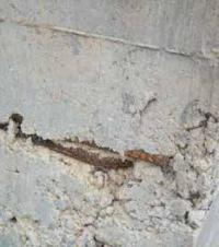
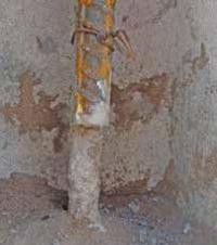
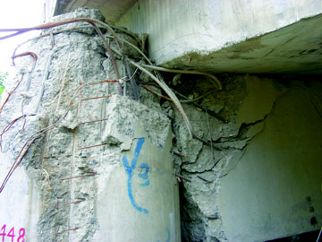
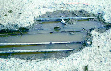
(2) Symptoms: Visual examination will typically reveal rust staining of the concrete. This staining will be followed by cracking. Cracks produced by corrosion generally run in straight, parallel lines at uniform intervals corresponding to the spacing of the reinforcement. As deterioration continues, spalling of the concrete over the reinforcing steel will occur with the reinforcing bar becoming visible (Figure 2-27). One area where labora- tory analysis may be beneficial is the determination of the chloride contents in the concrete. This procedure may be used to determine the amount of concrete to be removed during a rehabilitation project.
 |
(3) Prevention: ACI 201.2R describes the considera- tions for protecting reinforcing steel in concrete: use of concrete with low permeability; use of properly propor- tioned concrete having a low w/c; use of as low a con- crete slump as practical; use of good workmanship in placing the concrete; curing the concrete properly; provid- ing adequate concrete cover over the reinforcing steel; providing good drainage to prevent water from standing on the concrete; limiting chlorides in the concrete mix- ture; and paying careful attention to protruding items such as bolts or other anchors.
e. Design errors:
Design errors may be divided into two general types: those resulting from inadequate structural design and those resulting from lack of attention to relatively minor design details. Each of the two types of design errors is discussed below.
(1) Inadequate structural design:
- Mechanism: The failure mechanism is simple-- the concrete is exposed to greater stress than it is capable of carrying or it sustains greater strain than its strain capacity.
- Symptoms: Visual examinations of failures resulting from inadequate structural design will usually show one of two symptoms. First, errors in design result- ing in excessively high compressive stresses will result in spalling. Similarly, high torsion or shear stresses may also result in spalling or cracking. Second, high tensile stresses will result in cracking. To identify inadequate design as a cause of damage, the locations of the damage should be compared to the types of stresses that should be present in the concrete. For example, if spalls are present on the underside of a simple-supported beam, high com- pressive stresses are not present and inadequate design may be eliminated as a cause. However, if the type and location of the damage and the probable stress are in agreement, a detailed stress analysis will be required to determine whether inadequate design is the cause. Labo- ratory analysis is generally not applicable in the case of suspected inadequate design. However, for rehabilitation projects, thorough petrographic analysis and strength test- ing of concrete from elements to be reused will be necessary.
- Prevention: Inadequate design is best prevented by thorough and careful review of all design calculations. Any rehabilitation method that makes use of existing concrete structural members must be carefully reviewed.
 |
(2) Poor design details:
While a structure may be adequately designed to meet loadings and other overall requirements, poor detailing may result in localized con- centrations of high stresses in otherwise satisfactory con- crete. These high stresses may result in cracking that allows water or chemicals access to the concrete. In other cases, poor design detailing may simply allow water to pond on a structure, resulting in saturated concrete. In general, poor detailing does not lead directly to concrete failure; rather, it contributes to the action of one of the other causes of concrete deterioration described in this chapter. Several specific types of poor detailing and their possible effects on a structure are described in the fol- lowing paragraphs. In general, all of these problems can be prevented by a thorough and careful review of plans and specifications for the project. In the case of existing structures, problems resulting from poor detailing should be handled by correcting the detailing and not by simply responding to the symptoms.
 |
- Abrupt changes in section: Abrupt changes in section may cause stress concentrations that may result in cracking. Typical examples would include the use of relatively thin sections such as bridge decks rigidly tied into massive abutments or patches and replacement con- crete that are not uniform in plan dimensions.
- Insufficient reinforcement at reentrant corners and openings: Reentrant corners and openings also tend to cause stress concentrations that may cause cracking. In this case, the best prevention is to provide additional reinforcement in areas where stress concentrations are expected to occur.
- Inadequate provision for deflection: Deflections in excess of those anticipated may result in loading of members or sections beyond the capacities for which they were designed. Typically, these loadings will be induced in walls or partitions, resulting in cracking.
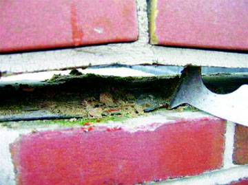
- Inadequate provision for drainage: Poor attention to the details of draining a structure may result in the ponding of water. This ponding may result in leakage or saturation of concrete. Leakage may result in damage to the interior of the structure or in staining and encrus- tations on the structure. Saturation may result in severely damaged concrete if the structure is in an area that is subjected to freezing and thawing.
- Insufficient travel in expansion joints: Inade- quately designed expansion joints may result in spalling of concrete adjacent to the joints. The full range of pos- sible temperature differentials that a concrete may be expected to experience should be taken into account in the specification for expansion joints. There is no single expansion joint that will work for all cases of temperature differential.
- Incompatibility of materials: The use of mate- rials with different properties (modulus of elasticity or coefficient of thermal expansion) adjacent to one another may result in cracking or spalling as the structure is loaded or as it is subjected to daily or annual temperature variations.
- Neglect of creep effect: Neglect of creep may have similar effects as noted earlier for inadequate provi- sion for deflections (paragraph 3-2e(2)(c)). Additionally, neglect of creep in prestressed concrete members may lead to excessive prestress loss that in turn results in cracking as loads are applied.
- Rigid joints between precast units: Designs utilizing precast elements must provide for movement between adjacent precast elements or between the precast elements and the supporting frame. Failure to provide for this movement can result in cracking or spalling.
- Unanticipated shear stresses in piers, columns, or abutments: If, through lack of maintenance, expansion bearing assembles are allowed to become frozen, horizon- tal loading may be transferred to the concrete elements supporting the bearings. The result will be cracking in the concrete, usually compounded by other problems which will be caused by the entry of water into the concrete.
- Inadequate joint spacing in slabs: This is one of the most frequent causes of cracking of slabs-on-grade. Guidance on joint spacing and depth of contraction joints may be found in ACI 332R.
 |
f. Abrasion:
Abrasion damage caused by water- borne debris and the techniques used to repair the damage on several Corps' structures are described by McDonald (1980). Also, causes of abrasion-erosion damage and procedures for repair and prevention of damage are described in ACI 210R.
 |
- Mechanism: Abrasion-erosion damage is caused by the action of debris rolling and grinding against a concrete surface. In hydraulic structures, the areas most likely to be damaged are spillway aprons, stilling basin slabs, and lock culverts and laterals. The sources of the debris include construction trash left in a structure, riprap brought back into a basin by eddy currents because of poor hydraulic design or asymmetrical discharge, and riprap or other debris thrown into a basin by the public. Also barges and towboats impacting or scraping on lock wells and guide wells can cause abrasions erosion damage.
- Symptoms: Concrete surfaces abraded by water- borne debris are generally smooth (Figure 2-20) and may contain localized depressions. Most of the debris remain- ing in the structure will be spherical and smooth. Mechanical abrasion is usually characterized by long shallow grooves in the concrete surface and spalling along monolith joints. Armor plates is often torn away or bent.
- Prevention: The following measures should be followed to prevent or minimize abrasion-erosion damage to concrete hydraulic structures (Liu 1980 and McDonald 1980).
 |
(a) Design: It appears that given appropriate flow conditions in the presence of debris, all of the construc- tion materials currently being used in hydraulic structures are to some degree susceptible to erosion. While improvements in materials should reduce the rate of con- crete damage caused by erosion, this improvement alone will not solve the problem. Until the adverse hydraulic conditions that can cause abrasion-erosion damage are minimized or eliminated, it will be extremely difficult for any of the construction materials currently being used to avoid damage by erosion. Prior to construction or repair of major structures, hydraulic model studies of the struc- ture may be required to identify potential causes of ero- sion damage and to evaluate the effectiveness of various modifications in eliminating those undesirable hydraulic conditions. Many older structures have spillways designed with a vertical end-sill. This design is usually efficient in trapping the erosion-causing debris within the spillway. In some structures, a 45-deg fillet installed on the upstream side of the end sill has resulted in a self- cleaning stilling basin. Recessing monolith joints in lock walls and guide walls will minimize stilling basin spalling caused by barge impact and abrasion (See paragraph 8-1e(2)(e)).
(b) Operation: In existing structures, balanced flows should be maintained into basins by using all gates to avoid discharge conditions where eddy action is prevalent. Substantial discharges that can provide a good hydraulic jump without creating eddy action should be released periodically in an attempt to flush debris from the stilling basin. Guidance as to discharge and tailwater relations required for flushing should be developed through model and prototype tests. Periodic inspections should be required to determine the presence of debris in the stilling basin and the extent of erosion. If the debris cannot be removed by flushing operations, the basin should be cleaned by other means.
 |
(c) Materials: It is imperative that materials be tested and evaluated, in accordance with ASTM C 1138 (CRD-C 63), prior to use in the repair of abrasion-erosion damaged hydraulic structures. Abrasion-resistant concrete should include the maximum amount of the hardest coarse aggregate that is available and the lowest practical w/c. In some cases where hard aggregate was not available, high-range water-reducing admixtures (HRWRA) and condensed silica fume have been used to develop igh compressive strength concrete 97 MPa (14,000 psi) to overcome problems of unsatisfactory aggregate (Holland 1983).). Apparently, at these high compressive strengths the hardened cement paste assumes a greater role in resisting abrasion-erosion damage, and as such, the aggregate quality becomes correspondingly less important. The abrasion-erosion resistance of vacuum-treated con- crete, polymer concrete, polymer-impregnated concrete, and polymer portland-cement concrete is significantly superior to that of comparable conventional concrete that can also be attributed to a stronger cement matrix. The increased costs associated with materials, production, and placing of these and any other special concretes in com- parison with conventional concrete should be considered during the evaluation process. While the addition of steel fibers would be expected to increase the impact resistance of concrete, fiber-reinforced concrete is consistently less resistant to abrasion-erosion than conventional concrete. Therefore, fiber-reinforced concrete should not be used for repair of stilling basins or other hydraulic structures where abrasion-erosion is of major concern. Several types of surface coatings have exhibited good abrasion- erosion resistance during laboratory tests. These include polyurethanes, epoxy-resin mortar, furan-resin mortar, acrylic mortar, and iron aggregate toppings. However, some difficulties have been reported in field applications of surface coatings, primarily the result of improper sur- face preparation and thermal incompatibility between coatings and concrete.
 |
g. Cavitation:
Cavitation-erosion is the result of relatively complex flow characteristics of water over concrete surfaces (ACI 210R).
(1) Mechanism: There is little evidence to show that water flowing over concrete surfaces at velocities less than 12.2 m/sec (40 ft/sec) causes any cavitation damage to the concrete. However, when the flow is fast enough (greater than 12.2 m/sec) and where there is surface irreg- ularity in the concrete, cavitation damage may occur. Whenever there is surface irregularity, the flowing water will separate from the concrete surface. In the area of separation from the concrete, vapor bubbles will develop because of the lowered vapor pressure in the region. As these bubbles are carried downstream, they will soon reach areas of normal pressure. These bubbles will col- lapse with an almost instantaneous reduction in volume. This collapse, or implosion, creates a shock wave which, upon reaching a concrete surface, induces very high stresses over a small area. The repeated collapse of vapor bubbles on or near the concrete surface will cause pitting. Concrete spillways and outlet works of many high dams have been severely damaged by cavitation.
(2) Symptoms: Concrete that has been damaged will be severely pitted and extremely rough (Figure 2-21). As the damage progresses, the roughness of the damaged area may induce additional cavitation.
(3) Prevention:
(a) Hydraulic design: Even the strongest materials cannot withstand the forces of cavitation indefinitely. Therefore, proper hydraulic design and the use of aeration to reduce or eliminate the parameters that trigger cavita- tion are extremely important (ACI 210R). Since these topics are beyond the scope of this manual, hydraulic engineers and appropriate hydraulic design manuals should be consulted.
(b) Conventional materials: While proper material selection can increase the cavitation resistance of concrete, the only totally effective solution is to reduce or eliminate the causes of cavitation. However, it is recognized that in the case of existing structures in need of repair, the reduc- tion or elimination of cavitation may be difficult and costly. The next best solution is to replace the damaged concrete with more cavitation-resistant materials. Cavita- tion resistance of concrete can be increased by use of a properly designed low w/c, high-strength concrete. The use of no larger than 38-mm (1-1/2-in.) nominal maxi- mum size aggregate is beneficial. Furthermore, methods which have reduced the unit water content of the mixture, such as use of a water-reducing admixture, are also bene- ficial. Vital to increased cavitation resistance are the use of hard, dense aggregate particles and a good aggregate- to-mortar bond. Typically, cement-based materials exhibit significantly lower resistance to cavitation compared to polymer-based materials.
(c) Other cavitation-resistant materials: Cavitation- damaged areas have been successfully repaired with steel- fiber concrete and polymer concrete (Houghton, Borge, and Paxton 1978). Some coatings, such as neoprene and polyurethane, have reduced cavitation damage to concrete, but since near-perfect adhesion to the concrete is critical, the use of the coatings is not common. Once a tear or a chip in the coating occurs, the entire coating is likely to be peeled off.
(d) Construction practices: Construction practices are of paramount importance when concrete surfaces are exposed to high-velocity flow, particularly if aeration devices are not incorporated in the design. Such surfaces must be as smooth as can be obtained under practical conditions. Accordingly, good construction practices as given in EM 1110-2-2000 should be followed whether the construction is new or is a repair. Formed and unformed surfaces should be carefully checked during each con- struction operation to confirm that they are within speci- fied tolerances. More restrictive tolerances on surfaces should be avoided since they become highly expensive to construct and often impractical to achieve, despite the use of modern equipment and good construction practices. Where possible, transverse joints in concrete conduits or chutes should be minimized. These joints are generally in a location where the greatest problem exists in maintain- ing a continuously smooth hydraulic surface. One con- struction technique which has proven satisfactory in placement of reasonably smooth hydraulic surfaces is the traveling slipform screed. This technique can be applied to tunnel inverts and to spillway chute slabs. Hurd (1989) provides information on the slipform screed. Since sur- face hardness improves cavitation resistance, proper cur- ing of these surfaces is essential.
h. Freezing and thawing:
 |
(1) Mechanism: As the temperature of a critically saturated concrete is lowered during cold weather, the freezable water held in the capillary pores of the cement paste and aggregates expands upon freezing. If subse- quent thawing is followed by refreezing, the concrete is further expanded, so that repeated cycles of freezing and thawing have a cumulative effect. By their very nature, concrete hydraulic structures are particularly vulnerable to freezing and thawing simply because there is ample opportunity for portions of these structures to become critically saturated. Concrete is especially vulnerable in areas of fluctuating water levels or under spraying condi- tions. Exposure in such areas as the tops of walls, piers, parapets, and slabs enhances the vulnerability of concrete to the harmful effects of repeated cycles of freezing and thawing. The use of deicing chemicals on concrete sur- faces may also accelerate damage caused by freezing and thawing and may lead to pitting and scaling. ACI 201.2R describes the action as physical. It involves the develop- ment of osmotic and hydraulic pressures during freezing, principally in the paste, similar to ordinary frost action.
 |
(2) Symptoms: Visual examination of concrete dam- aged by freezing and thawing may reveal symptoms rang- ing from surface scaling to extensive disintegration (Figure 2-10). Laboratory examination of cores taken from structures that show surficial effects of freezing and thawing will often show a series of cracks parallel to the surface of the structure.
(3) Prevention: The following preventive measures are recommended by ACI 201.2R for concrete that will be exposed to freezing and thawing while saturated:
- Designing the structure to minimize the exposure to moisture. For example, providing positive drainage rather than flat surfaces whenever possible.
- Using a concrete with a low w/c.
- Using adequate entrained air to provide a satisfac- tory air-void system in the concrete, i.e., a bubble spacing factor of 0.20 mm (0.008 in.) or less, which will provide protection for the anticipated service conditions and aggregate size. EM 1110-2-2000 provides information on the recommended amount of entrained air.
- Selecting suitable materials, particularly aggre- gates that perform well in properly proportioned concrete.
- Providing adequate curing to ensure that the com- pressive strength of the concrete is at least 24 MPa (3,500 psi) before the concrete is allowed to freeze in a saturated state.
i. Settlement and movement
(1) Mechanisms:
(a) Differential movement. Situations in which the various elements of a structure are moving with respect to one another are caused by differential movements. Since concrete structures are typically very rigid, they can toler- ate very little differential movement. As the differential movement increases, concrete members can be expected to be subjected to an overstressed condition. Ultimately, the members will crack or spall.
(b) Subsidence. Situations in which an entire struc- ture is moving or a single element of a structure, such as a monolith, is moving with respect to the remainder of the structure are caused by subsidence. In these cases, the concerns are not overcracking or spalling but rather stabil- ity against overturning or sliding. Whether portions of a single structural element are moving with respect to one another or whether entire elements are moving, the under- lying cause is more than likely to be a failure of the foun- dation material. This failure may be attributed to long-term consolidations, new loading conditions, or to a wide variety of other mechanisms. In situations in which structural movement is diagnosed as a cause of concrete deterioration, a thorough geotechnical investigation should be conducted.
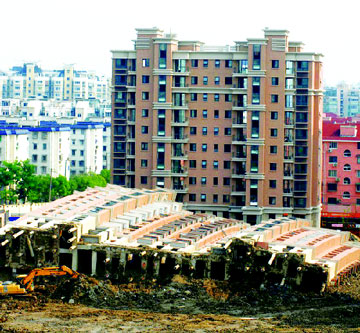
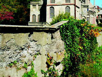
(2) Symptoms: Visual examination of structures undergoing settlement or movement will usually reveal cracking or spalling or faulty alignment of structural members. Very often, movement will be apparent in nonstructural members such as block or brick masonry walls. Another good indication of structural movement is an increase in the amount of water leaking into the struc- ture. Since differential settlement of the foundation of a structure is usually a long-term phenomenon, review of instrumentation data will be helpful in determining whether apparent movement is real. Review by structural and geotechnical engineering specialists will be required.
(3) Prevention: Prevention of settlements and move- ments or corrective measures are beyond the scope of this manual. Appropriate structural and geotechnical engi- neering manuals should be consulted for guidance.
j. Shrinkage
Shrinkage is caused by the loss of moisture from concrete. It may be divided into two gen- eral categories: that which occurs before setting (plastic shrinkage) and that which occurs after setting (drying shrinkage). Each of these types of shrinkage is discussed in this section.
(1) Plastic shrinkage:
(a) Mechanism: During the period between placing and setting, most concrete will exhibit bleeding to some degree. Bleeding is the appearance of moisture on the surface of the concrete; it is caused by the settling of the heavier components of the mixture. Usually, the bleed water evaporates slowly from the concrete surface. If environmental conditions are such that evaporation is occurring faster than water is being supplied to the sur- face by bleeding, high tensile stresses can develop. These stresses can lead to the development of cracks on the concrete surface.
(b) Symptoms: Cracking caused by plastic shrinkage will be seen within a few hours of concrete placement. Typically, the cracks are isolated rather than patterned. These cracks are generally wide and shallow.
(c) Prevention: Determination of whether the weather conditions on the day of the placement are conducive to plastic shrinkage cracking is necessary. If the predicted evaporation rate is high according to ACI 305R, appropri- ate actions such as erecting windbreaks, erecting shade over the placement, cooling the concrete, and misting should be taken after placement. Additionally, it will be beneficial to minimize the loss of moisture from the con- crete surface between placing and finishing. Finally, curing should be started as soon as is practical. If crack- ing caused by plastic shrinkage does occur and if it is detected early enough, revibration and refinishing of the cracked area will resolve the immediate problem of the cracks. Other measures as described above will be required to prevent additional occurrences.
(2) Drying shrinkage:
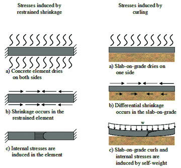
(a) Mechanism: Drying shrinkage is the long-term change in volume of concrete caused by the loss of mois- ture. If this shrinkage could take place without any restraint, there would be no damage to the concrete. However, the concrete in a structure is always subject to some degree of restraint by either the foundation, by another part of the structure, or by the difference in shrinkage between the concrete at the surface and that in the interior of a member. This restraint may also be attributed to purely physical conditions such as the place- ment of a footing on a rough foundation or to chemical bonding of new concrete to earlier placements or to both. The combination of shrinkage and restraints cause tensile stresses that can ultimately lead to cracking.
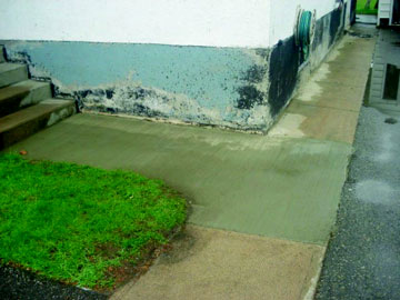
(b) Symptoms: Visual examination will typically show cracks that are characterized by their fineness and absence of any indication of movement. They are usually shallow, a few inches in depth. The crack pattern is typi- cally orthogonal or blocky. This type of surface cracking should not be confused with thermally induced deep cracking which occurs when dimensional change is restrained in newly placed concrete by rigid foundations or by old lifts of concrete..
(c) Prevention: In general, the approach is either to reduce the tendency of the concrete, to shrink or to reduce the restraint, or both. The following will help to reduce the tendency to shrink: use of less water in the concrete; use of larger aggregate to minimize paste content; placing the concrete at as low a temperature as practical; dam- pening the subgrade and the forms; dampening aggregates if they are dry and absorptive; and providing an adequate amount of reinforcement to distribute and reduce the size of cracks that do occur. Restraint can be reduced by providing adequate contraction joints.
k. Temperature changes
Changes in temperature cause a corresponding change in the volume of concrete. As was true for moisture-induced volume change (drying shrinkage), temperature-induced volume changes must be combined with restraint before damage can occur. Basi- cally, there are three temperature change phenomena that may cause damage to concrete. First, there are the tem- perature changes that are generated internally by the heat of hydration of cement in large placements. Second, there are the temperature changes generated by variations in climatic conditions. Finally, there is a special case of externally generated temperature change--fire damage. Internally and externally generated temperature changes are discussed in subsequent paragraphs. Because of the infrequent nature of its occurrence in civil works struc- tures, fire damage is not included in this manual
(1) Internally generated temperature differences.
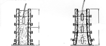
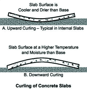
(a) Mechanism: The hydration of portland cement is an exothermic chemical reaction. In large volume place- ments, significant amounts of heat may be generated and the temperature of the concrete may be raised by more than 38 °C (100 °F) over the concrete temperature at placement. Usually, this temperature rise is not uniform throughout the mass of the concrete, and steep tempera- ture gradients may develop. These temperature gradients give rise to a situation known as internal restraint--the outer portions of the concrete may be losing heat while the inner portions are gaining (heat). If the differential is great, cracking may occur. Simultaneously with the development of this internal restraint condition, as the concrete mass begins to cool, a reduction in volume takes place. If the reduction in volume is prevented by external conditions (such as by chemical bonding, by mechanical interlock, or by piles or dowels extending into the con- crete), the concrete is externally restrained. If the strains induced by the external restraint are great enough, crack- ing may occur. There is increasing evidence, particularly for rehabilitation work, that relatively minor temperature differences in thin, highly restrained overlays can lead to cracking. Such cracking has been seen repeatedly in lock wall resurfacing (Figure 2-5) and in stilling basin overlays. Measured temperature differentials have typi- cally been much below those normally associated with thermally induced cracking.
 |
(b) Symptoms: Cracking resulting from internal restraint will be relatively shallow and isolated. Cracking resulting from external restraint will usually extend through the full section. Thermally induced cracking may be expected to be regularly spaced and perpendicular to the larger dimensions of the concrete.
(c) Prevention: An in-depth discussion of tempera- ture and cracking predictions for massive placements can be found in ACI 207.1R and ACI 207.2R. In general, the following may be beneficial: using as low a cement con- tent as possible; using a low-heat cement or combination of cement and pozzolans; placing the concrete at the minimum practical temperature; selecting aggregates with low moduli of elasticity and low coefficients of thermal expansion; cooling internally or insulating the placement as appropriate to minimizing temperature differentials; and minimizing the effects of stress concentrators that may instigate cracking.
(2) Externally generated temperature differences
(a) Mechanism: The basic failure mechanism in this case is the same as that for internally generated tempera- ture differences--the tensile strength of the concrete is exceeded. In this case the temperature change leading to the concrete volume change is caused by external factors, usually changing climatic conditions. This cause of deter- ioration is best described by the following examples: First, a pavement slab cast in the summer. As the air and ground temperatures drop in the fall and winter, the slab may undergo a temperature drop of 27 °C (80 °F), or more. Typical parameters for such a temperature drop (coefficient of thermal expansion of 10.8 × 10⁻⁶/°C (6 × 10⁻⁶/°F) indicate a 30-m (98-ft) slab would experience a shortening of more than 13 mm (1/2 in.). If the slab were restrained, such movement would certainly lead to crack- ing. Second, a foundation or retaining wall that is cast in the summer. In this case, as the weather cools, the con- crete may cool at different rates--exposed concrete will cool faster than that insulated by soil or other backfill. The restraint provided by this differential cooling may lead to cracking if adequate contraction joints have not been provided. Third, concrete that experiences sig- nificant expansion during the warmer portions of the year. Spalling may occur if there are no adequate expansion joints. In severe cases, pavement slabs may be lifted out of alignment, resulting in so-called blowups. Fourth, concretes that have been repaired or overlayed with materials that do not have the same coefficient of thermal expansion as the underlying material. Annual heating and cooling may lead to cracking or debonding of the two materials.
 |
(b) Symptoms: Visual examination will show regu- larly spaced cracking in the case of restrained contraction. Similarly, spalling at expansion joints will be seen in the case of restrained expansion. Problems resulting from expansion-contraction caused by thermal differences will be seen as pattern cracking, individual cracking, or spalling.
(c) Prevention: The best prevention is obviously to make provision for the use of contraction and expansion joints. Providing reinforcing steel (temperature steel) will help to distribute cracks and minimize the size of those that do occur. Careful review of the properties of all repair materials will help to eliminate problems caused by temperature changes
l. Weathering:
Weathering is frequently referred to as a cause of concrete deterioration. ACI 116R defines weathering as "Changes in color, texture, strength, chemi- cal composition, or other properties of a natural or artificial material due to the action of the weather." How- ever, since all of these effects may be more correctly attributed to other causes of concrete deterioration described in this chapter, weathering itself is not con- sidered to be a specific cause of deterioration.
Relating Symptoms to Causes of Distress and Deterioration
Given a detailed report of the condition of the concrete in a structure and a basic understanding of the various mech- anisms that can cause concrete deterioration, the problem becomes one of relating the observations or symptoms to the underlying causes. When many of the different causes of deterioration produce the same symptoms, the task of relating symptoms to causes is more difficult than it first appears. One procedure to consider is based upon that described by Johnson (1965). This procedure is obviously idealized and makes no attempt to deal with more than one cause that may be active at any one time. Although there will usually be a combination of causes responsible for the damage detected on a structure, this procedure should provide a starting point for an analysis.
a. Evaluate structure design to determine adequacy:
First consider what types of stress could have caused the observed symptoms. For example, tension will cause cracking, while compression will cause spalling. Torsion or shear will usually result in both cracking and spalling. If the basic symptom is disintegration, then overstress may be eliminated as a cause. Second, attempt to relate the probable types of stress causing the damage noted to the locations of the damage. For example, if cracking resulting from excessive tensile stress is suspected, it would not be consistent to find that type of damage in an area that is under compression. Next, if the damage seems appropriate for the location, attempt to relate the specific orientation of the damage to the stress pattern. Tension cracks should be roughly perpendicular to the line of externally induced stress. Shear usually causes failure by diagonal tension, in which the cracks will run diagonally in the concrete section. Visualizing the basic stress patterns in the structure will aid in this phase of the evaluation. If no inconsistency is encountered during this evaluation, then overstress may be the cause of the observed damage. A thorough stress analysis is warranted to confirm this finding. If an inconsistency has been detected, such as cracking in a compression zone, the next step in the procedure should be followed.
b. Relate the symptoms to potential causes:
| Table 3 Relating Symptoms to Causes of Distress and Deterioration of Concrete |
Causes
|
Construction Faults
|
Cracking |
Disintegration |
Distortion Movement
|
Erosion |
Joint Failures
|
Seepage |
Spalling |
| Accidental |
|
|
|
|
|
|
|
|
| Loadings |
|
X
|
|
|
|
|
|
|
| Chemical |
|
|
|
|
|
|
|
|
| Reactions |
|
X
|
X
|
|
|
|
|
|
| Construction |
|
|
|
|
|
|
X
|
|
| Errors |
X
|
X
|
|
|
|
X
|
X
|
X
|
| Corrosion |
|
X
|
|
|
|
|
|
X
|
| Design Errors |
|
X
|
|
|
|
X
|
X
|
X
|
| Erosion |
|
|
X
|
|
X
|
|
|
|
| Freezing and |
|
|
|
|
|
|
|
|
| Thawing |
|
X
|
X
|
|
|
|
|
X
|
| Settlement |
|
|
|
|
|
|
|
|
| And Movement |
|
X
|
|
X
|
|
X
|
|
X
|
| Shrinkage |
X
|
X
|
|
X
|
|
|
|
|
| Temperature |
|
|
|
|
|
X
|
|
|
| Changes |
|
X
|
|
|
|
|
|
X
|
For this step, Table 3-3 will be of benefit. Depending upon the symptom, it may be possible to eliminate several possible causes. For example, if the symptom is disintegration or erosion, several potential causes may be eliminated by this procedure.
c. Eliminate the readily identifiable causes:
From the list of possible causes remaining after symptoms have been related to potential causes, it may be possible to eliminate two causes very quickly since they are relatively easy to identify. The first of these is corrosion of embedded metals. It will be easy to verify whether the cracking and spalling noted are a result of corrosion. The second cause that is readily identified is accidental load- ing, since personnel at the structure should be able to relate the observed symptoms to a specific incident. Analyze the available clues. If no solution has been reached at this stage, all of the evidences generated by field and laboratory investigations should be carefully reviewed. Attention should be paid to the following points:
(1) If the basic symptom is that of disintegration of the concrete surface, then essentially three possible causes remain: chemical attack, erosion, and freezing and thaw- ing. Attempts should be made to relate the nature and type of the damage to the location in the structure and to the environment of the concrete in determining which of the three possibilities is the most likely to be the cause of the damage.
(2) If there is evidence of swelling of the concrete, then there are two possibilities: chemical reactions and temperature changes. Destructive chemical reactions such as alkali-silica or alkali-carbonate attack that cause swel- ling will have been identified during the laboratory inves- tigation. Temperature-induced swelling should be ruled out unless there is additional evidence such as spalling at joints.
(3) If the evidence is spalling and corrosion and accidental loadings have been eliminated earlier, the major causes of spalling remaining are construction errors, poor detailing, freezing and thawing, and externally generated temperature changes. Examination of the structure should have provided evidence as to the location and general nature of the spalling that will allow identification of the exact cause.
(4) If the evidence is cracking, then construction errors, shrinkage, temperature changes, settlement and movement, chemical reactions, and poor design details remain as possible causes of distress and deterioration of concrete. Each of these possibilities will have to be reviewed in light of the available laboratory and field observations to establish which is responsible.
(5) If the evidence is seepage and it has not been related to a detrimental internal chemical reaction by this time, then it is probably the result of design errors or construction errors, such as improper location or installa- tion of a waterstop. e. Determine why the deterioration has occurred. Once the basic cause or causes of the damage have been established, there remains one final requirement: to understand how the causal agent acted upon the concrete. For example, if the symptoms were cracking and spalling and the cause was corrosion of the reinforcing steel, what facilitated the corrosion? Was there chloride in the con- crete? Was there inadequate cover over the reinforcing steel? Another example to consider is concrete damage caused by freezing and thawing. Did the damage occur because the concrete did not contain an adequate air-void system, or did the damage occur because the concrete used was not expected to be saturated but, for whatever reason, was saturated? Only when the cause and its mode of action are completely understood should the next step of selecting a repair material be attempted.