Construction of Tunnel
By Shachindra S Bhat
Introduction
Tunnelling is a rapidly growing concept today due to its advantages and also due to advance technologies available for the purpose of execution. Generally tunnel can be defined as,
- A long, narrow, essentially linear excavated underground opening, the length of which greatly exceeds its width or height. It is generally considered as one of the hazardous and specialized engineering & construction project.
- Serves the purpose of transportation, conveyance of materials, approach to underground mines, defence and escape routes.
- Tunnel Engineering can be discussed under major sub heads i.e. Geological features and rock mechanics, Design and engineering, Methods of Tunnelling, Optimization of cycle time and Safety in tunnelling.
Challenges Galore
Tunnelling always comes with challenges and surprises. The Geology determines feasibility and the cost. Engineering properties of rock determines changes in conditions such as time, rate and direction of advance etc,. Groundwater is the most difficult parameter. Drilling core in advance for geotechnical investigation only recovers less than 0.0005% of the excavated volume of the tunnel and hence it is almost not possible to predict with accuracy about anticipated geology.
Evaluation of rock properties
Rock mass parameters for the analysis and design of tunnels are evaluated by conducting in-situ tests in rock mass and laboratory tests on rock cores. Magnitude and direction of in-situ stresses are very important parameters to decide the orientation and support system for underground excavation.
Site characterization
Site characterization of tunnel depends on topography of the area, the climate and the accessibility of the area and location of the tunnel with respect to the ground surface and rock formation boundaries.
Structural stability of the rock body, which is a function of seismicity, faults, and stress concentrations and Hydrologic regime and its perturbation - which is a function of the permeability of the ground and the ground water flow rates are also important.
Other important aspects of site characterisation are,
- Rock types in the rock mass, their genesis and their homogeneity.
- Degree of weathering and weather ability of the rock.
- Geologic discontinuities and other defects.
- Deformability characteristics under short and long term loading.
Stand up time of tunnel
It is the time period the ground will safely stand by itself at the heading, thus providing a period for installing the supports. The stand up time depends on the strength of rock mass/soil.
- Stand-up time can be
- Immediate for soft ground
- Few minutes for very poor rock
- Few hours for poor rock
- Few days for fair rock
- Few months for good rock
- Years for very good rock
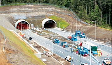
Access to tunnel
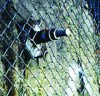
Typical photo of tunnel access is shown in fig (i) and (ii)
 |
| Fig 1 |
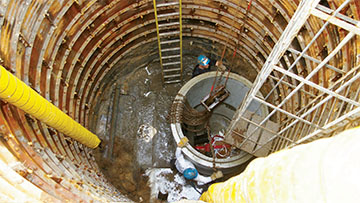
In case of long tunnels adits are introduced in-between, to enable construction operation from multiple faces. The position size and shape of adit is decided based on construction methodology being adopted. Land availability and land acquisition possibility also needs to be considered while finalizing entrance to tunnel. In hilly terrain where it is not possible to provide horizontal adit entry to tunnel, the next possible option is to provide vertical or inclined shafts. Construction operation through shaft is quite different when compared to horizontal adits and fig (iii) shows a typical vertical shaft and fig (IV) shows general arrangement outside the shaft for operation.
 |
| Fig 2 |
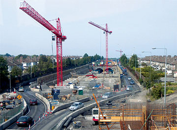 |
| Fig 3 - Outside Operations |
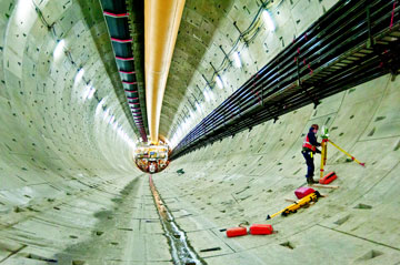
Tunnel Survey
Generally initial survey will be carried out from the already established centreline and benchmark. After each blast accurate survey will be carried. In order to save time and to have quick cycle of operations, laser beams are used. Two laser beams will be installed on the side of the tunnel and one in crown in case of large diameter tunnel. Surveyor will mark the profile for drilling from projected laser points. Advanced equipments will have inbuilt programme for profile marking and necessary corrections will be carried after each blast. Fig (V) shows laser survey inside tunnel.
 |
| Fig 4 - Tunnel Inside Survey |
Tunnel supports
Tunnel supporting system is generally done with temporary and permanent supports. To prevent dilation of rock, shotcrete is done on rock surface in layers. Wire mesh can be provided on rock surface before shotcrete as per design requirements. Shotcrete can be also done with steel fiber and is called as SFRS (Steel fiber reinforced shotcrete). Rock bolts are provided of appropriate length and diameter with cement and resin capsules. Expansion shells or wedges are provided for rock bolts.
| Typical rock bolt
Temporary and permanent steel supports are provided in such rocks which exert positive pressures within a short period of blasting. RCC precast laggings are used for covering the gap between such supports and the gap between support and rock surface is filled with backfill concrete of suitable grade.
Tunnel supports are provided depending upon rock classification and recommendation of competent authority at site. Fore poling, lattice girder supports, pipe roofing are some other methods of supports which are used under specific requirements.
Methods of tunnelling:
- Drill and blast method
- Using Jack hammer and Pusher-leg
- Using Drill jumbo
|
 |
| Fig 5 - Typical Rock Bolt |
- Tunnelling by boring
- Road headers
- TBMs
- Box pushing or Pipe jacking
- New Austrian Tunnelling Method
Tunnelling By Drill and Blast Method
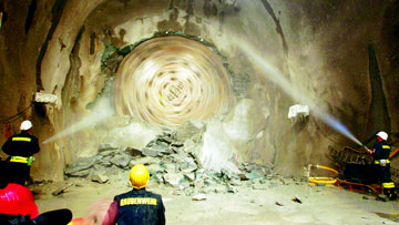 |
| Fig 6 Tunnelling By Drill Method |
This is considered as conventional method of tunnelling. The method consists of drilling controlled number of holes to a designated depth and then loading the holes with an appropriate blasting agent. Loaded holes are detonated and excavated / blasted rock is removed using heavy machineries such as loader / excavators etc., Efficiency and perfection depends on the skill to allow the explosive energy to be directed in the right direction. For optimum and safe tunnelling every strata and change in section need trial blast. Probe holes are drilled in advance to obtain advance information with regard to geology and strata being encountered.
 |
| Fig 7 Tunnelling By Blast Method |
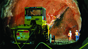
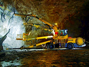
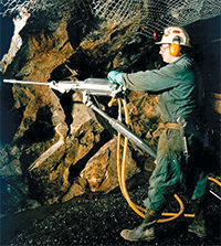
Drilling operation in tunnel
Drilling in tunnel is carried out with Jack hammer (Fig 8) and Pusher legs (Fig 9). In case of long tunnels and mechanized operations, tunnel boomers are deployed (Fig 10) for speedy operation and perfection in drilling. Selection technique depends on nature of the project or end use of the rock face, geology, drilling equipment available and associated cost. Generally 45mm dia holes are designed adopting either burn cut or wedge cut method depending on geology of the particular section.
 |
| Fig 9 |
It is very important while carrying out drilling to ensure designed profile of tunnel surface. The pattern of drilling adopted must ensure proper cut after the blast and there should not be either under cut or over cut from designed section. In order to exercise strict control on drilling and finished profile, different techniques are used while drilling, such as,
- Line drilling
- Pre-splitting
- Smooth blasting
Line drilling: This involves drilling of a row of closely spaced small holes of dia 50-75 mm along the final excavation line. Line drilled holes not loaded with explosive. Line-drilled holes provide a plane of weakness to which the final row of blast-holes can break. Maximum depth to which line holes can be drilled is seldom 10m.
Pre-Splitting: Pre-splitting or pre-shearing involves drilling a row of holes along the excavation line, similar to line-drilling. Peripheral holes are lightly charged and blasted prior to the primary blast. This Creates a fracture zone along the excavation line causing a discontinuity and minimises or eliminates the over break. This method is best carried out when the burden is of homogenous consolidated rock that is resistant to shifting.
It is extremely important to find the right hole spacing and charges for a particular type of rock. The limitation of this method is, this needs a separate cycle of drilling and blasting for the peripheral holes ahead of the primary blast and hence require additional time.
Smooth blasting: This Involves drilling holes along the excavation line, but blasting them after the primary blast. The Aim is trimming the excess material from the tunnel walls and to improve their stability. This is the most common method used in underground openings to control over break. Burden is reasonably finite in smooth blasting whereas it is infinite in pre-splitting.
 |
 |
| Fig 8 |
Fig 10 |
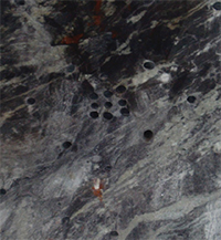
Drilling pattern: Based on its purpose, individual drilled holes in a pattern of drilling are grouped under different nomenclature. From cut hole to lifter hole, specific time delay is used while blasting to ensure continuity in blasting operation and proper fragmentation of rock. Fig (10) shows a typical drilled section of a tunnel with relief and cut holes.
Key parameters which defines the efficiency of blasting operation include,
- Pull [ face advance/depth of round]
- Specific charge or powder factor [ kg of explosive / m3 ]
- Specific drilling [ m of drilling / m3]
Blast induced rock mass damage or under-cut or over-break
The drilling pattern could be either Fan cut or V-cut or parallel cut. In each case the delay detonator numbers are organized for maximum output depending on type of rock strata encountered.
Charging and blasting operation in tunnel
Blasting using explosive is a specialized job in tunnelling which is carried by well experienced and authorized personnel only. Stringent safety measures are always taken before this activity and work will be executed in line with various statutory norms.
An explosive material is a semi-solid or liquid, which changes itself into large volumes of gas at high temperature and pressure when flame/heat or sudden shock is applied to it. Generally explosives are identified as Low explosives and High explosives. It is also categorized on specific generation such as 1st generation, 2nd / 3rd generation explosives.
Low explosives: A variety of blasting material falls in to this category such as, Gunpowder, flares etc. It is a mixture of a combustible substance and an oxidant and is cheap, stable, safe to handle, easily manufactured. They are fired by safety fuse and a long duration flame is produced.
High explosives: Nitroglycerine, ammonium nitrate, TNT falls under this category. These are blasted with the help of detonators. They are cap-sensitive and have high shattering effect with a detonating rate of 1000 to 9000 m/s.
Emulsion explosives: This is a two-phase system in which an inner or dispersed phase is distributed in an outer or continuous phase. In this case both the oxidizer and the fuel are liquids. It has a unique feature where in minute droplets of nitrate solution is tightly compacted within the continuous fuel phase. Velocity of detonation could be 5000 to 6000 m/s
Slurry explosives: This has Jelly like consistency. It is a mixture of an oxidizer and fuel sensitizer in aqueous medium, thickened with a gum. It is highly water resistant and contains low non-toxic fumes. Generally its shelf life is one year.
 |
| Fig 11 |
 |
Detonation: An explosive material needs to be detonated with an external device. Such device which is used to trigger an explosive material to have explosion can be initiated chemically, mechanically or electrically.
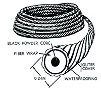
A plain detonator is fired by safety fuse Fig (11) and spark from the fuse causes explosion.
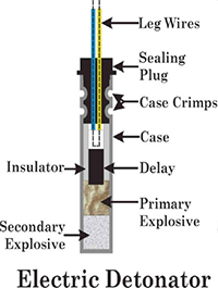
An Electrical detonator is fired by passage of electric current through the detonator.
Delay detonators are low tension electric detonators, but with a delay element. Fig (12). They usually comes as nano second / instantaneous electrical detonators, half second / long period delay detonators, milli second / short period delay detonators.
|
| Fig 12 |
|
Tunnelling by boring method
Sometimes conventional tunnelling methods are not preferred for underground / tunnelling works in specific areas as they pose increased risk to structures in the vicinity of tunnel excavation besides slower progress. Road headers and tunnel boring machines are preferred for tunnelling under such conditions.
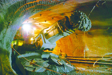 |
| Road Headers |
TBM's however on the other hand offer several advantages over the conventional techniques, such as
- Due to no use of explosives it is suitable in densely build-up areas and vibration level is less
- Excellent control on over break and due to erection of immediate support system , it is very safe method of tunnelling
- Rate of progress is faster and early completion of project results in overall saving of time and cost
- Reduces surface settlement to very low levels resulting in assured safety to adjoining structures.
The disadvantages could be,
- Circular section is possible. Other sections such as D shape, horse shoe shape, modified horse shoe shape etc., cannot be done.
- High initial working capital
- High to very high skilled work force required
- Construction Power requirement is very huge.
- In case of eventualities, time required for retrieving and re start of work requires substantial time. Majority of machine parts are imported and requires long lead.
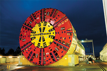 |
| Tunnel Boring Machine |
Tunneling by NATM
New Austrian Tunneling Method is more a strategy than a method. This helps in achieving tunnel stabilization by controlled stress release. Systematic rock bolting and shotcrete lining along with excavation is the most important feature. This method allows limited deformation but prevents loosening of rock.
Depending upon rock classification, shotcrete application can be slightly delayed, but should be applied within the stand-up time. The rock mass in the immediate vicinity of the excavated line is made to act as a loading member, together with the supporting system.
In short, NATM's principles are -
- Mobilizing rock mass strength,
- Shotcrete protection for preserving load carrying capacity of the rock mass,
- Monitoring the deformation of the excavated rock mass,
- Providing flexible, but active supports and
- Closing of invert to form a load bearing support ring to control deformation of the rock mass
Optimization
Tunnel operation is carried by following specific cycle time. A standard cycle time looks as shown in the chart.
- Tunnelling is a linear process and only optimizing each process will result in the overall improvement of cycle time. Charging, mucking and support installation need more control. Cycle time depends much on the geology and skill of operators of machines and blasters for effective blasting techniques suiting to the geology.
- An effective and quick cycle of mucking is essential by adopting suitable equipments. Equipment selection is very important and due care should be taken while finalizing the same. Proper ventilation and defuming system along with efficient dewatering system is required for healthy and effective tunnelling operation.
- Tunnel concrete lining & Grouting
Tunnel concrete lining gantry / shutter
Concrete lining of the tunnel is carried out generally in three phases i.e., Kerb beam, invert and overt. After laying the kerb beam a well designed tunnel shutter or gantry is erected on kerb beam. Overt concrete is then placed as per design mix in specified lengths which generally varies from 6 to 9m. Final part of concrete lining i.e., invert is laid after completion of overt concrete lining. Before completion of all activities, as per design, contact and consolidation grouting will be done.
Tunnel Safety
Safety is of paramount importance while working inside and outside tunnel. Due to unknown geological features, possibility of leak of gas, heavy seepage, slush and mud flow, upheaval and deformation, formation of cavities and collapse zones, it is extremely important to monitor safety implementation. Seepage generally varies from wet condition to dripping and flow condition. In case of excessive seepage immediate measures to control the same needs to be taken. Such measures can come in the form of pre grouting or post grouting. Sometimes ground freezing measures needs to be adopted to control seepage when it is not possible to control the same with conventional measures.
Apart from use of standard PPE's, display of safety boards, training workers and staff, evacuation facilities during emergency should be practiced without fail. Monitoring oxygen level and detection of presence of other gas beyond acceptable limits needs to be carried frequently. Proper ventilation system is very essential. A well designed ventilation system with sufficient capacity fans and suitable sized ducts should be provided. It is recommended to use less diesel operated equipments and more electrical equipments inside the tunnel to keep emission and pollution level well under control.
Author: